

Reflection -type photointerrupter
- Summary
- Abstract
- Description
- Claims
- Application Information
AI Technical Summary
Benefits of technology
Problems solved by technology
Method used
Image

Examples
first embodiment
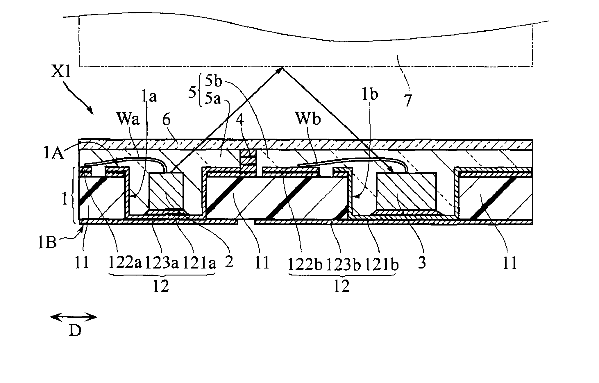
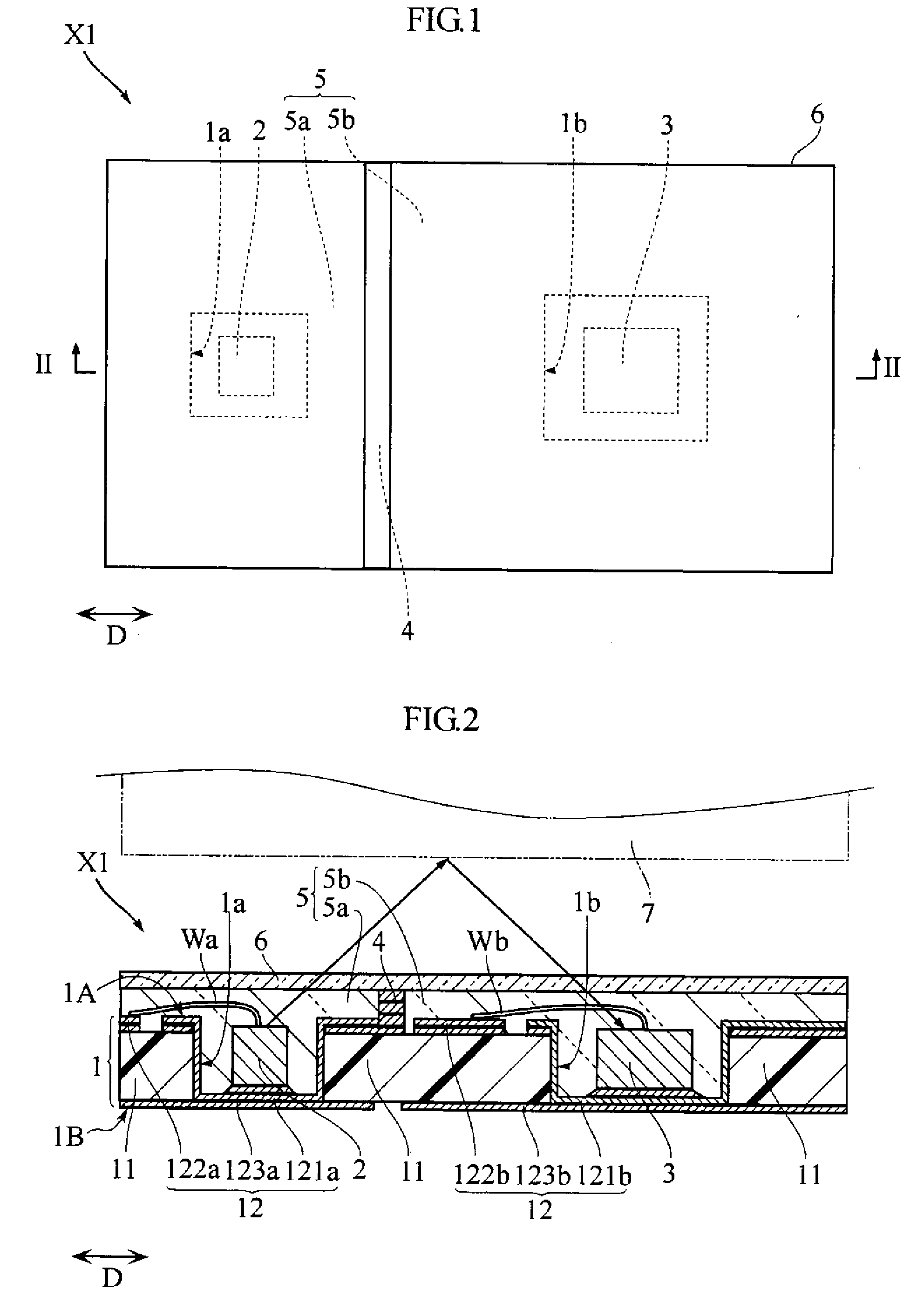
[0034]FIGS. 1 and 2 illustrate a reflection-type photointerrupter X1 according to the present invention. The photointerrupter X1 includes a substrate 1, a light emitting element 2, a light receiving element 3, a projection 4, a molded resin 5 and a reflection film 6. The outer shape of the photointerrupter X1 shown in FIG. 1 has a size of e.g. 1.4 mm×1.3 mm. The thickness of the photointerrupter X1 shown in FIG. 2 is e.g. 0.1 to 0.2 mm. The photointerrupter X1 may be incorporated in e g. a foldable mobile phone to detect the open / close state of the mobile phone.
[0035]The substrate 1 includes a first surface 1A, a second surface 1B, and recesses 1a and 1b which are open in the first surface 1A side. The substrate 1 includes a base member 11 and a wiring pattern 12.
[0036]The base member 11 is made of e.g. a glass fiber-reinforced epoxy resin and in the form of a rectangular plate having a size of e.g. 1.9 mm×1.3 mm. The thickness of the base member 11 is e.g. 0.05 mm. The base member ...
second embodiment
[0065]FIG. 5 is a sectional view illustrating a photointerrupter X2 according to the present invention. The photointerrupter X2 includes a substrate 1, a light emitting element 2, a light receiving element 3, a projection 4′ and a molded resin 5. The photointerrupter X2 is different from the foregoing photointerrupter X1 in that the pad electrodes 121a, 121b are spaced from the mount electrodes 123a, 123b, a projection 4′ is provided instead of the projection 4, the reflection film 6 is eliminated and the molded resin 5 includes lens portions 5a′, 5b′.
[0066]The projection 4′ is provided on the first surface 1A between the recesses 1a and 1b of the substrate 1 and made of a resin material which blocks infrared light. The upper end of the projection 4′ in the figure reaches the upper end of the molded resin 5 in the figure. The projection 4′ is formed on the first surface 1A before the molded resin 5 is formed on the first surface 1A side of the substrate I.
[0067]The lens portion 5a′...
third embodiment
[0074]FIG. 6 is a sectional view illustrating a photointerrupter X3 according to the present invention. The photointerrupter X3 includes a substrate 1, a light emitting element 2, a light receiving element 3, a projection 4 and a molded resin 5. The photointerrupter X3 is different from the foregoing photointerrupter X1 in that the reflection film 6 is eliminated and the molded resin 5 includes a surface 5′.
[0075]The surface 5′ of the molded resin 5 of the photointerrupter X3 is the upper end surface of the molded resin 5 in FIG. 6 and includes minute irregularities formed by graining or engraving. The difference in height of the minute irregularities of the surface 5′ is e.g. 1 to 20 μm.
[0076]The photointerrupter X3 having the above-described structure is suitable for thickness reduction for the same reasons as those described above with respect to the photointerrupter X1. Further, the photointerrupter X3 is suitable for achieving high heat dissipation efficiency for the same reaso...
PUM
 Abstract
Description
Claims
Application Information