Method for estimating a radar cross-section

a radar cross-section and cross-section technology, applied in the field of radar signature, can solve the problems of increasing the cost of building an anechoic chamber for objects of large sizes, increasing the cost of measurement, and increasing the difficulty of obtaining the rcs by measuremen

Inactive Publication Date: 2010-05-06
COMMISSARIAT A LENERGIE ATOMIQUE ET AUX ENERGIES ALTERNATIVES
View PDF6 Cites 19 Cited by
  • Summary
  • Abstract
  • Description
  • Claims
  • Application Information

AI Technical Summary

Benefits of technology

[0046]In the latter case, the matrix reconditioning steps may also be iterated as long as the

Problems solved by technology

Obtaining the RCS by a measurement has many limitations.
First of all, it is very expensive to build an anechoic chamber for objects of large sizes.
This problem is further worsened at low frequency where the efficiency of the absorbents is less.
Finally, only a few measurements of RCS values are generally carried out typically according to a few relative bearing angles in an equatorial plane, so that only a rather meagre two-dimensional representation of the targ

Method used


Image

  • Method for estimating a radar cross-section
  • Method for estimating a radar cross-section
  • Method for estimating a radar cross-section

Examples


Embodiment Construction

[0055]A target will be considered subsequently, for which it is desired to estimate the monostatic or bistatic RCS, preferentially but not exclusively, at low frequency, in the sense as defined above.

[0056]Generally, for a given frequency f, the description of the bistatic RCS of the target may be expressed as a matrix with a size 2N×2N:

Σb=(σ11HHσ12HH…σ1NHHσ11HVσ12HV…σ1NHVσ21HHσ22HH…σ2NHHσ21HVσ22HV…σ2NHV⋮⋮⋱⋮⋮⋮⋱⋮σN1HHσN2HH…σNNHHσN1HVσN2HV…σNNHVσ11VHσ12VH…σ1NVHσ11VVσ12VV…σ1NVVσ21VHσ22VH…σ2NVHσ21VVσ22VV…σ2NVV⋮⋮⋱⋮⋮⋮⋱⋮σN1VHσN2VH…σNNVHσN1VVσN2VV…σNNVV)(3)

[0057]wherein each element σijπeπr is the value of the observed RCS for an incident wave of direction {right arrow over (u)}ie, of polarization πe=H or V and for a receiving direction {right arrow over (u)}jr with polarization πr=H or V. The directions {right arrow over (u)}ie and {right arrow over (u)}jr, i, j=1, . . . , N are advantageously but not necessarily equidistributed within the solid angle 4π. For example, these directions may ...


PUM


Abstract

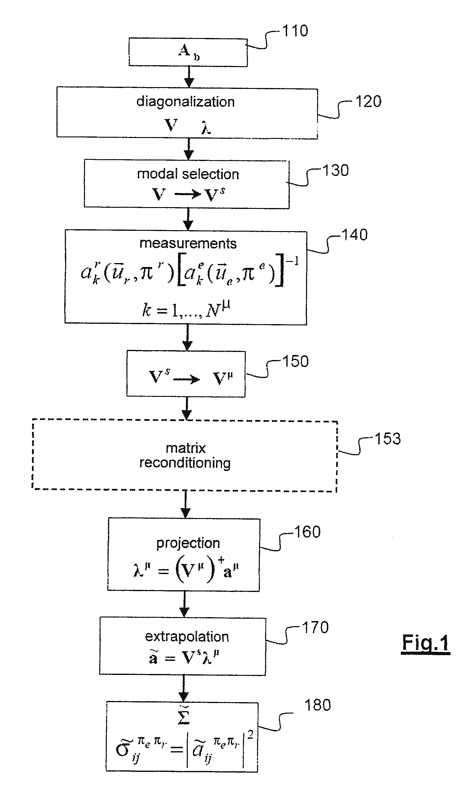
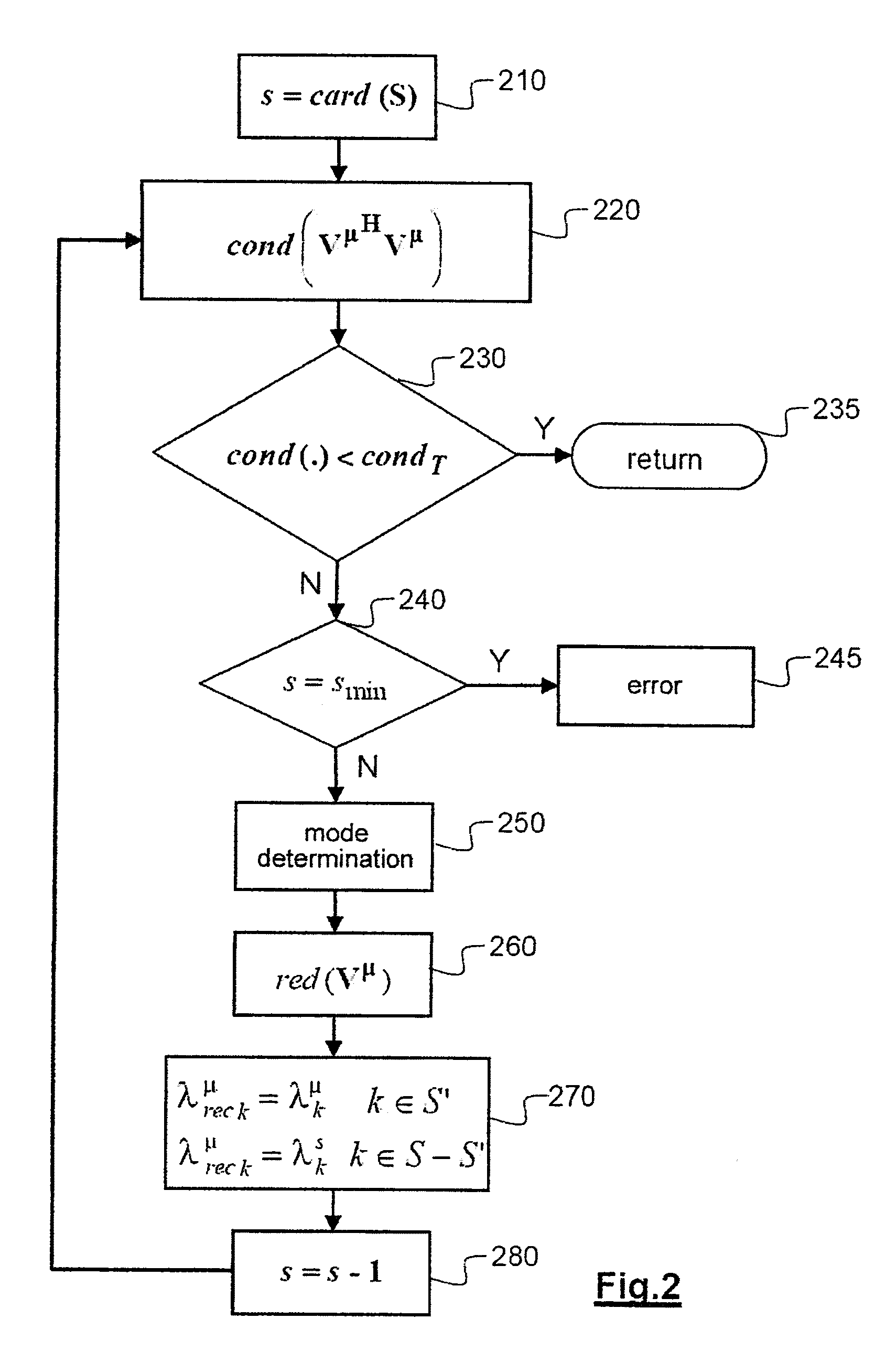
A method for estimating a radar cross-section (RES) of a given object by using a diffraction model of this object. With the model, it is possible to determine a basis adapted to said object on which is projected a vector of measurement. With the projected vector, it is possible to obtain a more complete reconstructed vector than the measurement vector in terms of incident wave and diffracted wave observation directions/polarizations and the components of which have a better signal/noise ratio than the measurements. The reconstructed vector is then used for calculating the RCS.

Description

CROSS REFERENCE TO RELATED APPLICATIONS OR PRIORITY CLAIM[0001]This application is a national phase of International Application No. PCT / EP2008 / 054026, entitled “METHOD OF ESTIMATION OF EQUIVALENT RADAR SURFACE”, which was filed on Apr. 3, 2008, and which claims priority of French Patent Application No. 07 54251, filed Apr. 3, 2007.DESCRIPTION[0002]1. Technical Field[0003]The present invention relates to the field of radar signature and more particularly to the determination of a radar cross-section.[0004]2. State of the Prior Art[0005]The radar cross-section or RCS is a fundamental quantity characteristic of a target. It is used both in the military field and in the civil field (for example air control) with the purposes of discriminating an object, typically an aircraft.[0006]The RCS of a radar target is conventionally defined from assessment of the power of the wave emitted towards the target and of the power of the wave received by the radar. In the far field and by approximatin...

Claims


Application Information

Patent Timeline
IPC IPC(8): G01S13/00
CPCG01S7/41
Inventor VACUS, OLIVIERMORVAN, SYLVAIN
Owner COMMISSARIAT A LENERGIE ATOMIQUE ET AUX ENERGIES ALTERNATIVES
Why Eureka
Try Eureka