Wireless image transferring apparatus, wireless image receiving apparatus and wireless image transmitting apparatus, and wireless image transferring method, wireless image receiving method and wireless image transmitting method

a wireless image and wireless image technology, applied in closed circuit television systems, television systems, instruments, etc., can solve the problems of affecting color reproducibility, causing various kinds of inconvenience, and a large amount of inconvenience, so as to reduce delay and improve quality.

Inactive Publication Date: 2010-05-06
JVC KENWOOD CORP A CORP OF JAPAN
View PDF7 Cites 12 Cited by
  • Summary
  • Abstract
  • Description
  • Claims
  • Application Information

AI Technical Summary

Benefits of technology

[0012]The present invention has been made to solve the problems as mentioned above, and a purpose thereof is to provide a wireless image transferring apparatus, a wireless image receiving apparatus and the like capable of displaying real-time moving images with high quality and reduced delay.

Problems solved by technology

This may adversely affect the color reproducibility.
Where a transmitting side that wirelessly transmits camera image data or the like and a receiving side that receives the camera image data or the like transmitted wirelessly from the transmitting side are asynchronous and untuned with each other, there is concern that various kinds of inconvenience may be caused.
With much deviation in synchronization therebetween, frames or the like that constitute a part of an object image are lost, for example, and the frames are displayed in an overlapped manner, thus causing a great deal of inconvenience such as degradation in the quality of images displayed.

Method used


Image

  • Wireless image transferring apparatus, wireless image receiving apparatus and wireless image transmitting apparatus, and wireless image transferring method, wireless image receiving method and wireless image transmitting method
  • Wireless image transferring apparatus, wireless image receiving apparatus and wireless image transmitting apparatus, and wireless image transferring method, wireless image receiving method and wireless image transmitting method
  • Wireless image transferring apparatus, wireless image receiving apparatus and wireless image transmitting apparatus, and wireless image transferring method, wireless image receiving method and wireless image transmitting method

Examples


first embodiment

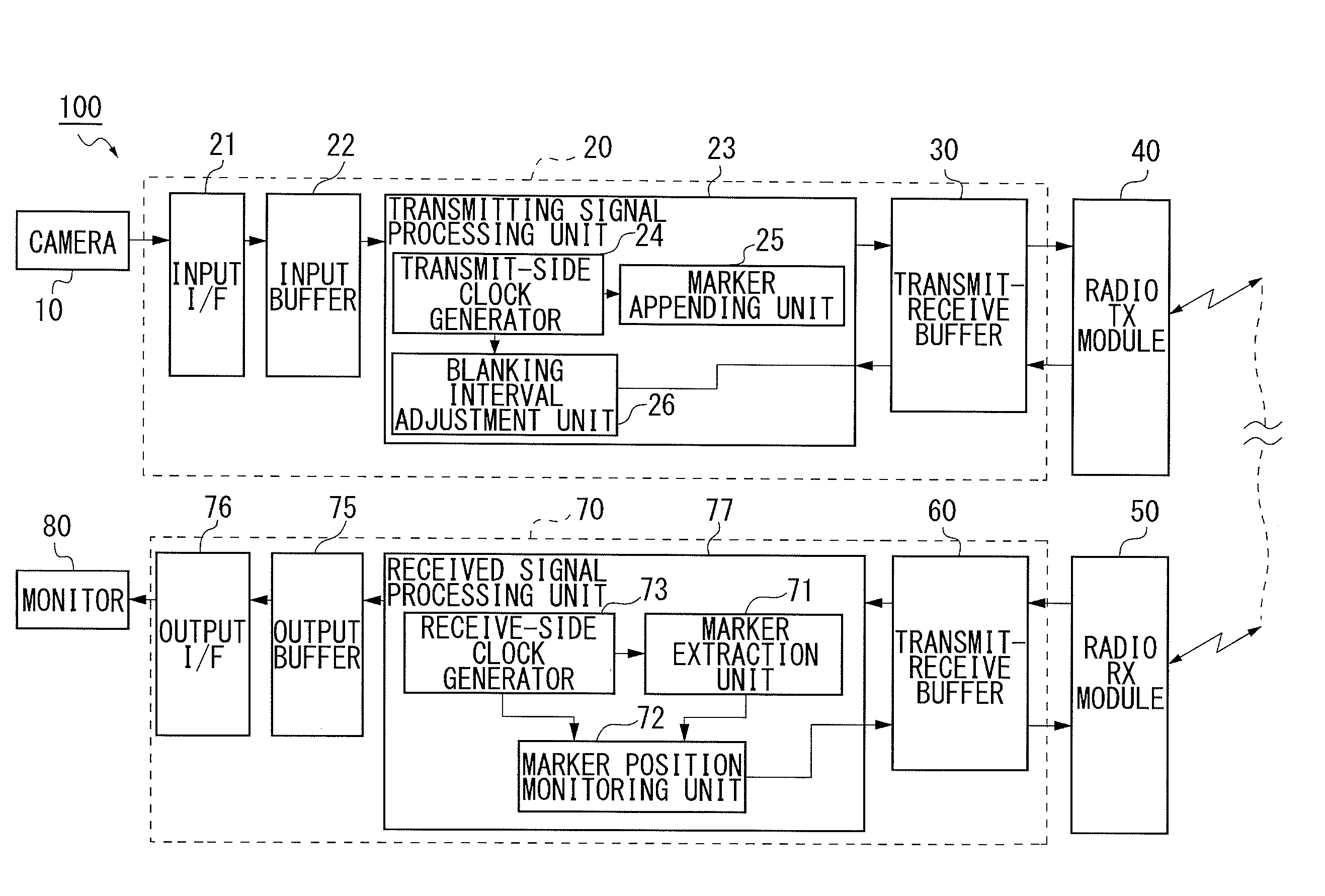
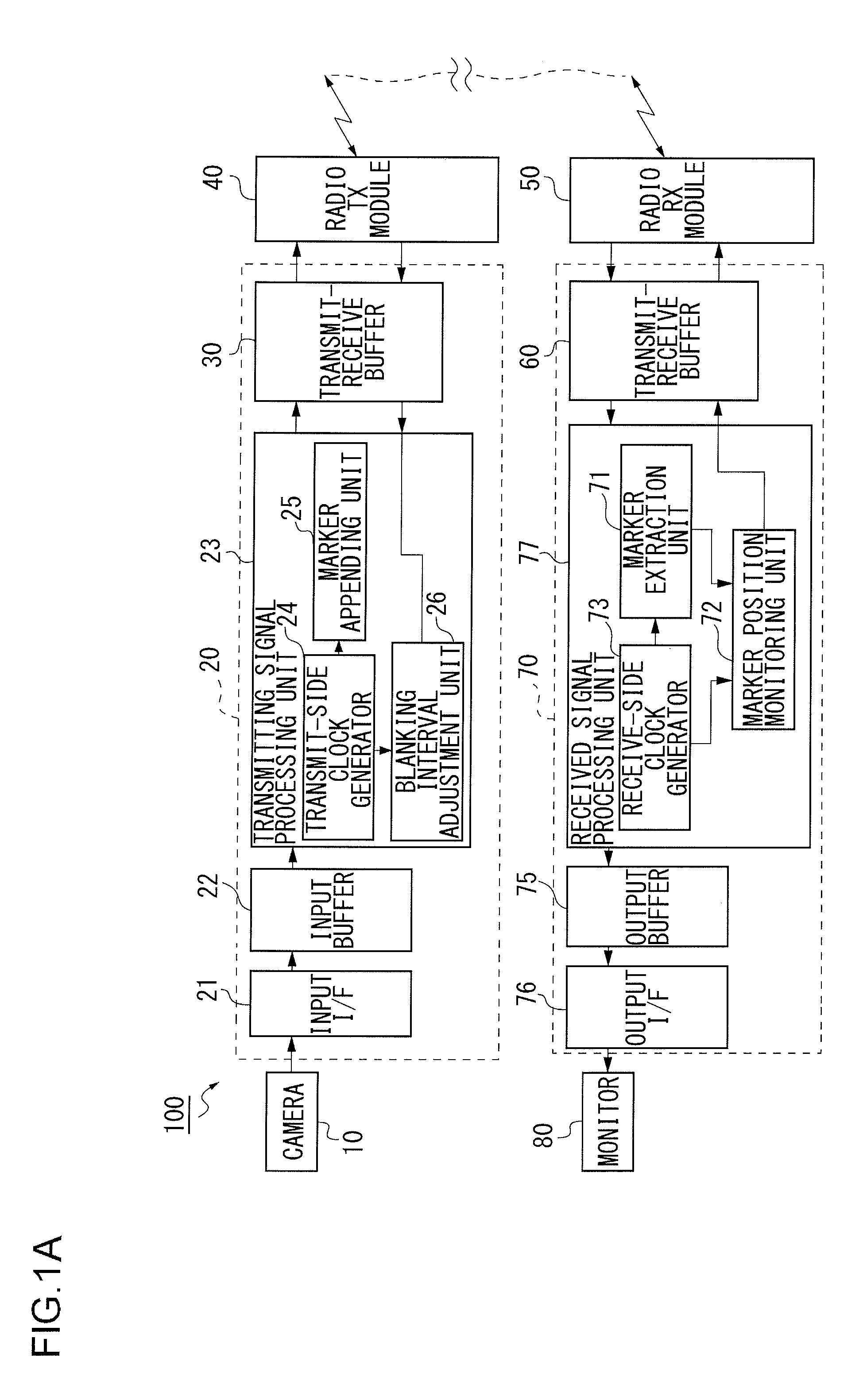
[0048]FIG. 1A illustrates a system structure of an automotive wireless image transferring apparatus 100. The automotive wireless image transferring apparatus 100 includes a rearview camera 10 provided at the back of a vehicle.

[0049]The image data of an object picked up by the camera 10 are inputted to a transmit-side unit 20 wherein the object is located in the back of the vehicle. The image data, which are subjected to a predetermined transmission processing and the like in the transmit-side unit 20, are temporarily stored in a transmit-receive buffer 30 and are wirelessly sent from a radio TX module 40.

[0050]The image data transmitted from the radio TX module 40 of the automotive wireless image transferring apparatus 100 are received by a radio RX module 50. The image data received by the radio RX module 50 are stored temporarily in a transmit-receive buffer 60 and are subjected to a predetermined receiving processing in a receive-side unit 70.

[0051]The image data processed by the...

second embodiment

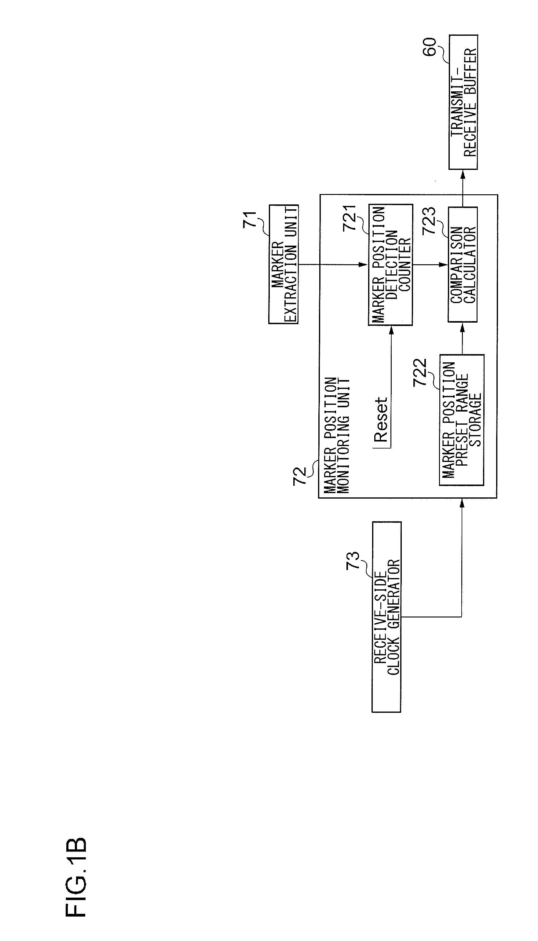
[0129]A description is next given of a case, according to a second embodiment, where the synchronization adjustment amount is calculated based on the marker position and so forth by a transmit-side unit 20. That is, in the second embodiment, a receive-side unit 70 detects the marker position only and feeds back the marker positional information (typically the counter value) to the transit-side unit 20, and the transmit-side unit 20 calculates a deviation amount from a marker allowable range T and a necessary adjustment amount associated with the deviation amount. A description is hereinbelow given of the second embodiment centering around differences from the automotive wireless image transferring apparatus 100 exemplified in the first embodiment. And components identical to or equivalent to those of the first embodiment are given the same reference numerals and the repeated explanation thereof is omitted here.

[0130]In an automotive wireless image transferring apparatus 100 accordin...


PUM


Abstract

A wireless image transferring apparatus includes a free-run transmitter and a free-run receiver. The free-run transmitter includes a marker appending unit for appending a vertical synchronization marker to image data and a nondisplay period adjustment unit for adjusting the length of nondisplay period of image data according to monitoring information supplied, the transmitter transmitting the image data and receiving the monitoring information. The free-run receiver includes a marker extraction unit for extracting the vertical synchronization marker from the image data received and a marker position monitoring unit for monitoring whether the position of a marker in the image data containing the vertical synchronization marker extracted by the marker extraction unit lies within a predetermined range or not and generating the monitoring information containing a synchronization adjustment amount used to expand or contract the nondisplay period of the image data such that the position of a marker lies within the predetermined range if the position of a marker lies outside the predetermined range, the receiver receiving the image data and feeding back the monitoring information to the transmitter.

Description

CROSS-REFERENCE TO RELATED APPLICATIONS[0001]The present application claims the priority benefit of Japanese patent application number 2008-280309 filed Oct. 30, 2009, the disclosure of which is incorporated herein by reference.BACKGROUND OF THE INVENTION[0002]1, Field of the Invention[0003]The present invention relates to a wireless image transferring apparatus, a wireless image receiving apparatus and the like capable of displaying a highly reliable object image.[0004]2. Description of the Related Art[0005]Where a camera for picking up images of an object and a liquid crystal display (LCD) device or the like for displaying the images of an object picked up by the camera are separated away from each other, it is necessary that the data of object images captured by the camera be transferred from the camera to the display device within a desired time period.[0006]For example, a conventional system implementing such a wireless image transferring method is a camera system where a synch...

Claims


Application Information

Patent Timeline
Patent Type & Authority Applications(United States)
IPC IPC(8): H04N5/10H04N5/38H04N5/44H04N5/073H04N7/18
CPCG09G2370/12H04N5/04H04N5/073
Inventor OWASHI, MIKIOKATSUMATA, NOBORU
Owner JVC KENWOOD CORP A CORP OF JAPAN
Why Eureka
Try Eureka