Threaded Retention Device for Downhole Transmission Lines

Active Publication Date: 2010-05-06
INTELLISERV
View PDF18 Cites 55 Cited by
  • Summary
  • Abstract
  • Description
  • Claims
  • Application Information

AI Technical Summary

Benefits of technology

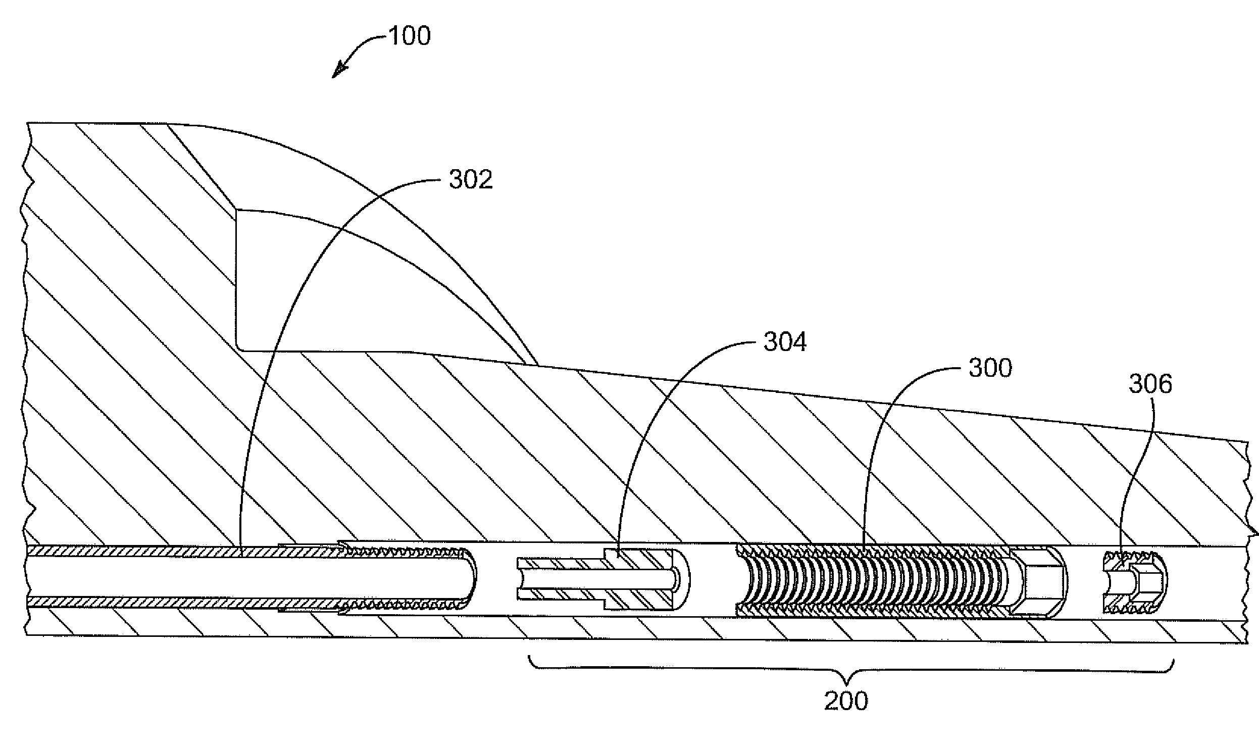
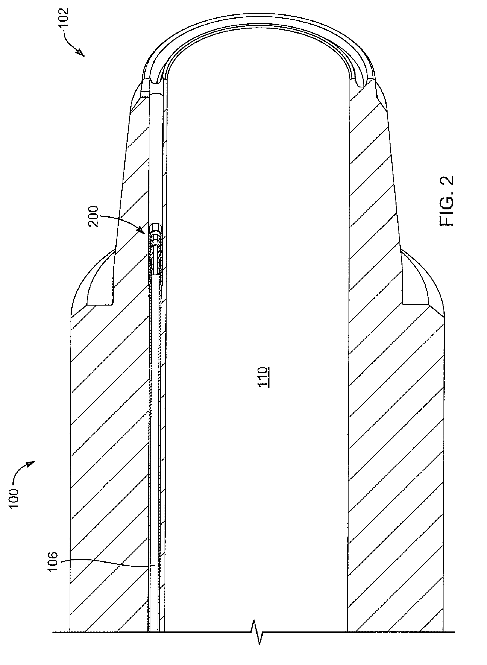
[0009]In certain aspects, an outer surface of the nut element is substantially cylindrical, allowing the nut element to slide within a cylindrical borehole formed in the downhole tool. Similarly, an outer surface of the externally threaded transmission line may also be substantially cylindrical. In selected embodiments, the outer diameter of the nut element is larger than the outer diameter of the externally threaded transmission line. This will allow the nut element to abut against a counterbore feature in the downhole tool, thereby retaining and maintaining tension in the transmission line.
[0010]In selected aspects, an elastomeric seal member may be inserted into the pa

Problems solved by technology

This allows the nut element to thread onto the external threads of the transmission line, there

Method used


Image

  • Threaded Retention Device for Downhole Transmission Lines
  • Threaded Retention Device for Downhole Transmission Lines
  • Threaded Retention Device for Downhole Transmission Lines

Examples


Example

[0026]It will be readily understood that the components of the present invention, as generally described and illustrated in the Figures herein, could be arranged and designed in a wide variety of different configurations. Thus, the following more detailed description of embodiments of apparatus and methods of the present invention, as represented in the Figures, is not intended to limit the scope of the invention, as claimed, but is merely representative of various selected embodiments of the invention.

[0027]The illustrated embodiments of the invention will be best understood by reference to the drawings, wherein like parts are designated by like numerals throughout. Those of ordinary skill in the art will, of course, appreciate that various modifications to the apparatus and methods described herein may be easily made without departing from the essential characteristics of the invention, as described in connection with the Figures. Thus, the following description of the Figures is ...


PUM


Abstract

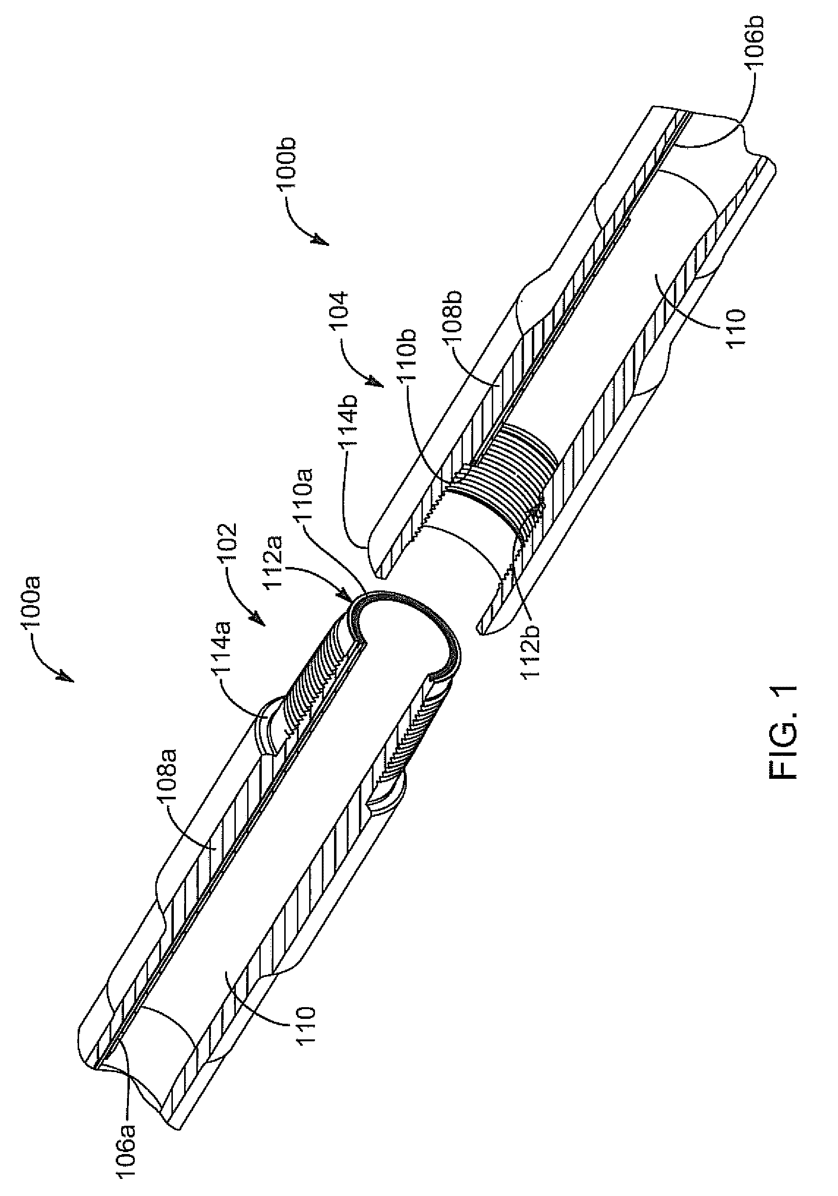
An apparatus for retaining and tensioning an end of a transmission line includes a nut element having internal threads configured to engage an externally threaded transmission line, such as an externally threaded coaxial cable, thereby retaining an end of the transmission line. The internal threads may form a passageway extending from a first end of the nut element to a second end of the nut element. This passageway may allow a transmission line to pass through the nut element. A socket may be incorporated into one end of the nut element to enable a tool to apply torque thereto. A corresponding method is also disclosed.

Description

BACKGROUND[0001]1. Field of the Invention[0002]This invention relates to downhole drilling, and more particularly to apparatus and methods for retaining and tensioning transmission lines in downhole tools.[0003]2. Description of the Related Art[0004]For half a century, the oil and gas industry has sought to develop downhole telemetry systems that enable high-definition formation evaluation and borehole navigation while drilling in real time. The ability to transmit large amounts of sub-surface data to the surface has the potential to significantly decrease drilling costs by enabling operators to more accurately direct the drill string to hydrocarbon deposits. Such information may also improve safety and reduce the environmental impacts of drilling. This technology may also be desirable to take advantage of numerous advances in the design of tools and techniques for oil and gas exploration, and may be used to provide real-time access to data such as temperature, pressure, inclination...

Claims


Application Information

Patent Timeline
IPC IPC(8): E21B47/12F16B7/18
CPCE21B17/023E21B17/042E21B47/12Y10T403/68Y10T403/18
Inventor HASSELL, TRENTLOHANI, PRABESH
Owner INTELLISERV
Why Eureka
Try Eureka