Counter-flow membraneless fuel cell

Inactive Publication Date: 2010-05-06
ARIZONA STATE UNIVERSITY
View PDF17 Cites 24 Cited by
  • Summary
  • Abstract
  • Description
  • Claims
  • Application Information

AI Technical Summary

Benefits of technology

[0008]According to an aspect of the present invention, there is provided a method for generating electrical current using a fuel cell comprising an anode, a cathode, a first flow channel associated with the anode, a second flow channel associated with the cathode, and a plurality of spaced apart exchange zones wherein the first and second flow channels are open to one another. The method includes flowing a first flow comprising a fuel and a first electrolyte through the first channel. The fuel is oxidized at the anode to generate electrons for conduction to a load and oxidation products in t

Problems solved by technology

Many of these problems are associated with the presence of the proton exchange membrane, which is highly sensitive to various factors, such as operating temperatures and membrane humidity.
This approach carries all the cost and efficiency issues associated with larger scale PEM fuel cells.
Moreover, the reduction in size exaggerates some of these problems, and introduces even further problems that require resolution for a commercially viable product.
First, the fuel and oxidizer will mix downstream of the entry point, wasting the majority of the fuel.
Second, the diffusivity of many oxidizers leads to mixed potentials at the anode due to oxidizer cross-over to the anode.
This takes energy away from the circuit and also leads to inefficiency of the overall cell.
Third, a mass transport boundary layer builds up on the electrodes which generates mass transport losses in the fuel cell and decreases performance.
Fourth, the architecture of the cell is restricted to the geometries, length scales, and electrolytes where laminar flow is ensured.
First, the amount of some oxidizers that can be typically carried by an electrolyte is relatively low (e.g., the oxygen solubility in an electrolyte is typically quite low relative to fuel solubility).
But increasing the flow rate requires increased work, thus detracting from the overall power efficiency of the cell.
Increasing the flow rate also advects the reactants downstream before they can fully react, resulting wasted reactants.
Because the designs in these two publications rely primarily on the use of selective electrodes for both the cathode and anode, this further detracts from the efficiency of the cell.

Method used


Image

  • Counter-flow membraneless fuel cell
  • Counter-flow membraneless fuel cell
  • Counter-flow membraneless fuel cell

Examples


Embodiment Construction

[0022]The Figures illustrate several embodiments of various aspects of the inventions claimed. These embodiments are in no way intended to be limiting, and are intended only as an example for facilitating an understanding of the principles of the claimed inventions. In some instances, various components are illustrated schematically, as it is understood many different structures may be used.

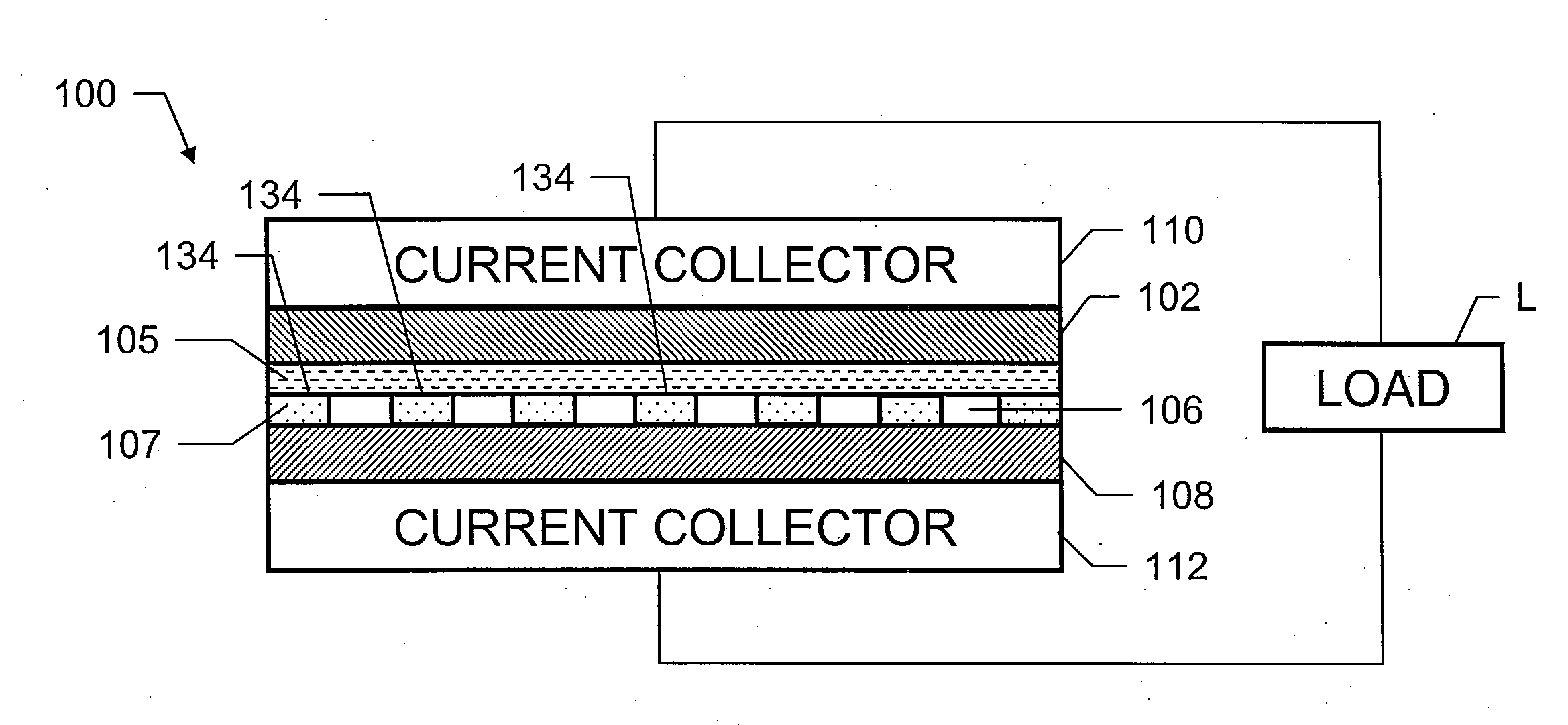
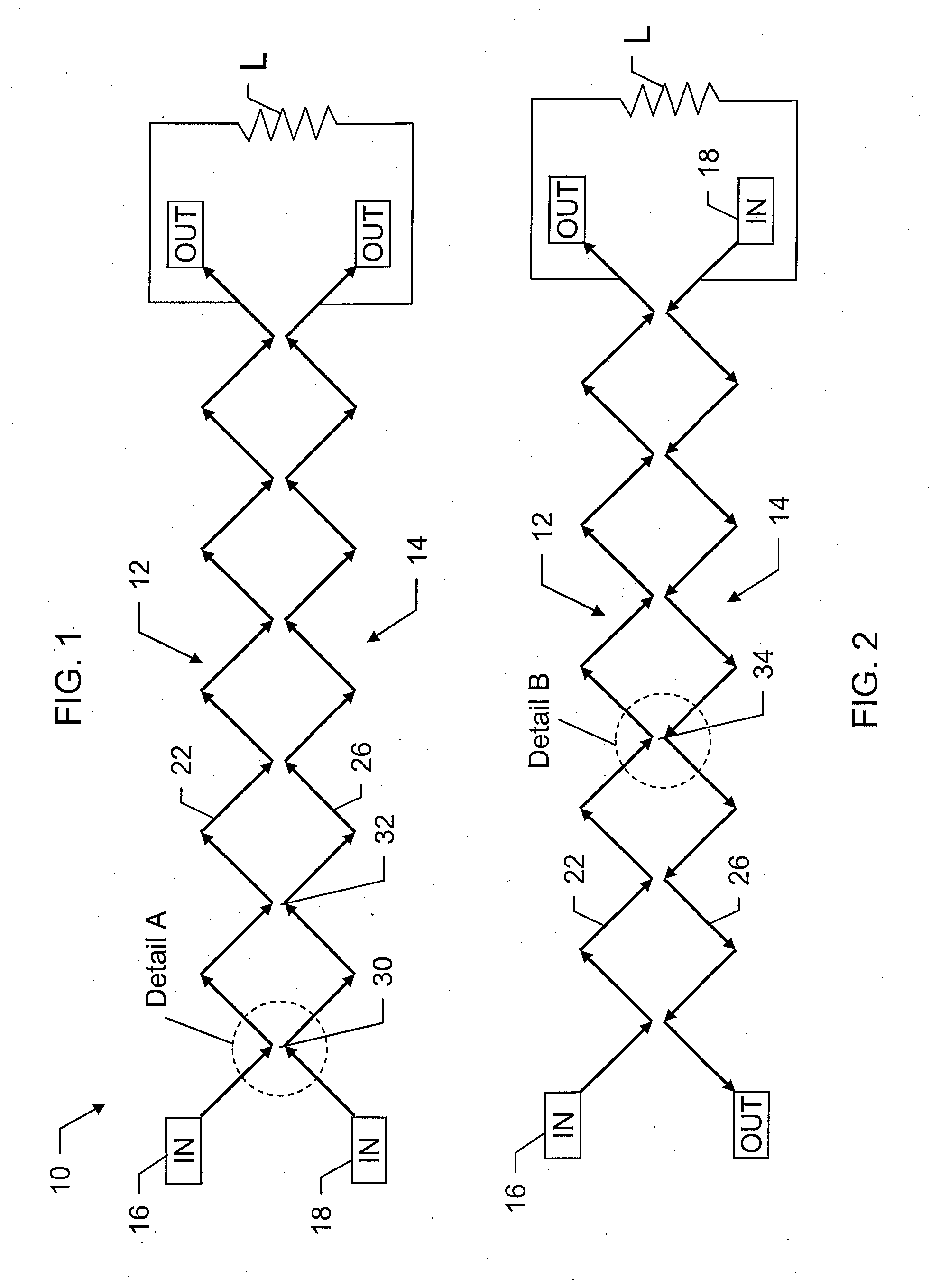
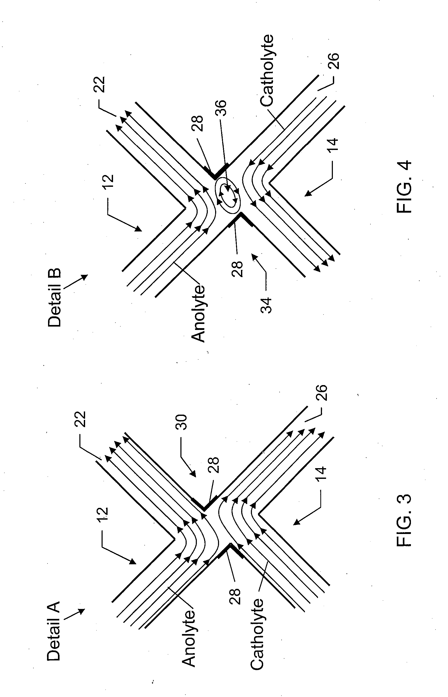
[0023]In the illustrated embodiment of FIG. 1, a fuel cell system is generally indicated at 10. The fuel cell system 10 has an anode 12 and a cathode 14 that are each connected to a load L. The anode 12 and the cathode 14 may be solid in embodiments where the respective fluids flow across or along the anode and the cathode, or may be wholly or partially porous in embodiments where the respective fluid flow through the anode and the cathode, as discussed in further detail below. The system 10 also includes a fuel source 16 configured to supply a fuel, which may be mixed with an electrolyte, an oxi...


PUM


Abstract

A method for generating electrical current using a fuel cell includes flowing a first flow that includes a fuel and an electrolyte through a first channel. The fuel is oxidized at an anode to generate electrons for conduction to a load and oxidation products that remain in the first flow. The method includes flowing a second flow that includes an oxidizer and an electrolyte through a second channel that is open to the first channel. A cathode receives electrons from the load and the oxidation products, and the oxidizer is reduced to form reduction products and complete an electrochemical circuit. The plurality of exchange zones are positioned and the flows are oriented within their respective first and second channels such that the first and second flows contact one another intermittently at the exchange zones to enable transport of the reduction and oxidation products to the anode and cathode.

Description

CROSS-REFERENCE TO RELATED APPLICATIONS [0001]This application claims the benefit of priority from U.S. Provisional Patent Application No. 61 / 193,157, filed Oct. 31, 2008, the entire content of which is incorporated herein by reference.FIELD OF THE INVENTION [0002]The present application relates to a fuel cell, and more particularly a membraneless fuel cell wherein a flow of reductant and oxidant are provided to a transport zone in which ions are exchanged and the reductant and oxidant undergo oxidation and reduction, respectively.BACKGROUND OF THE INVENTION[0003]If fuel cells are to become viable portable power sources in the future, solutions to a number of difficult, persistent technical problems are needed. Many of these problems are associated with the presence of the proton exchange membrane, which is highly sensitive to various factors, such as operating temperatures and membrane humidity. Efforts in portable applications have largely focused on reducing the size of proton ex...

Claims


Application Information

Patent Timeline
IPC IPC(8): H01M8/04H01M8/00H01M2/00
CPCH01M8/023H01M8/0258H01M8/04186H01M8/1004Y02E60/50
Inventor SALLOUM, KAMILPOSNER, JONATHAN
Owner ARIZONA STATE UNIVERSITY
Why Eureka
Try Eureka