Dental abutment analog for implant-secured restoration

a technology of dental abutments and implants, which is applied in the field of dental abutment analogs for implant-secured restorations, can solve the problems of lack of angularity, difficulty, if not impossible, in ensuring that the central axes of each implant processed by the oral surgeon are in fact parallel, etc., and achieves the effect of controlling costs and improving efficiency

Inactive Publication Date: 2010-05-06
CHAPEL TIMOTHY DOW
View PDF18 Cites 13 Cited by
  • Summary
  • Abstract
  • Description
  • Claims
  • Application Information

AI Technical Summary

Benefits of technology

[0014]It is an advantage of a dental abutment analog according to the present invention that thread timing of a dental implant involving an angle correction feature is accurately transferable to a model of the patient's mouth, assuring that a restoration device fabricated and assembled primarily in a laboratory will fit in the patient's mouth without difficulty.
[0015]It is an advantage of the present method that an implant-based dental restoration device employing angle-corrected abutment studs may be fabricated primarily in a dental laboratory, without the need for a dentist and patient to engage in aligning and cementing or otherwise fastening angle correction com...

Problems solved by technology

Typically, a problem faced by dentists in executing an implant-based restoration arises from the fact that it is very difficult to assure that the central axes of each of the implants processed by the oral surgeon are in fact parallel to one another.
This is important because implants have threaded cavities into which denture attaching abutments are placed, and if the lack of parallelism between abutments is extreme, it may be difficult, if not impossible, to insert a denture without considerable angular adjustments to the fastenings which are affixed to the screwed-in abutments.
This lack of angularity requires dentists to cement angular adjusting devices to the abutments, while working inside the patient's mouth.
This is undesirable because achieving the desired parallel orientation may be very time consuming, and also requires the handling of exceedingly ...

Method used


Image

  • Dental abutment analog for implant-secured restoration
  • Dental abutment analog for implant-secured restoration
  • Dental abutment analog for implant-secured restoration

Examples


Embodiment Construction

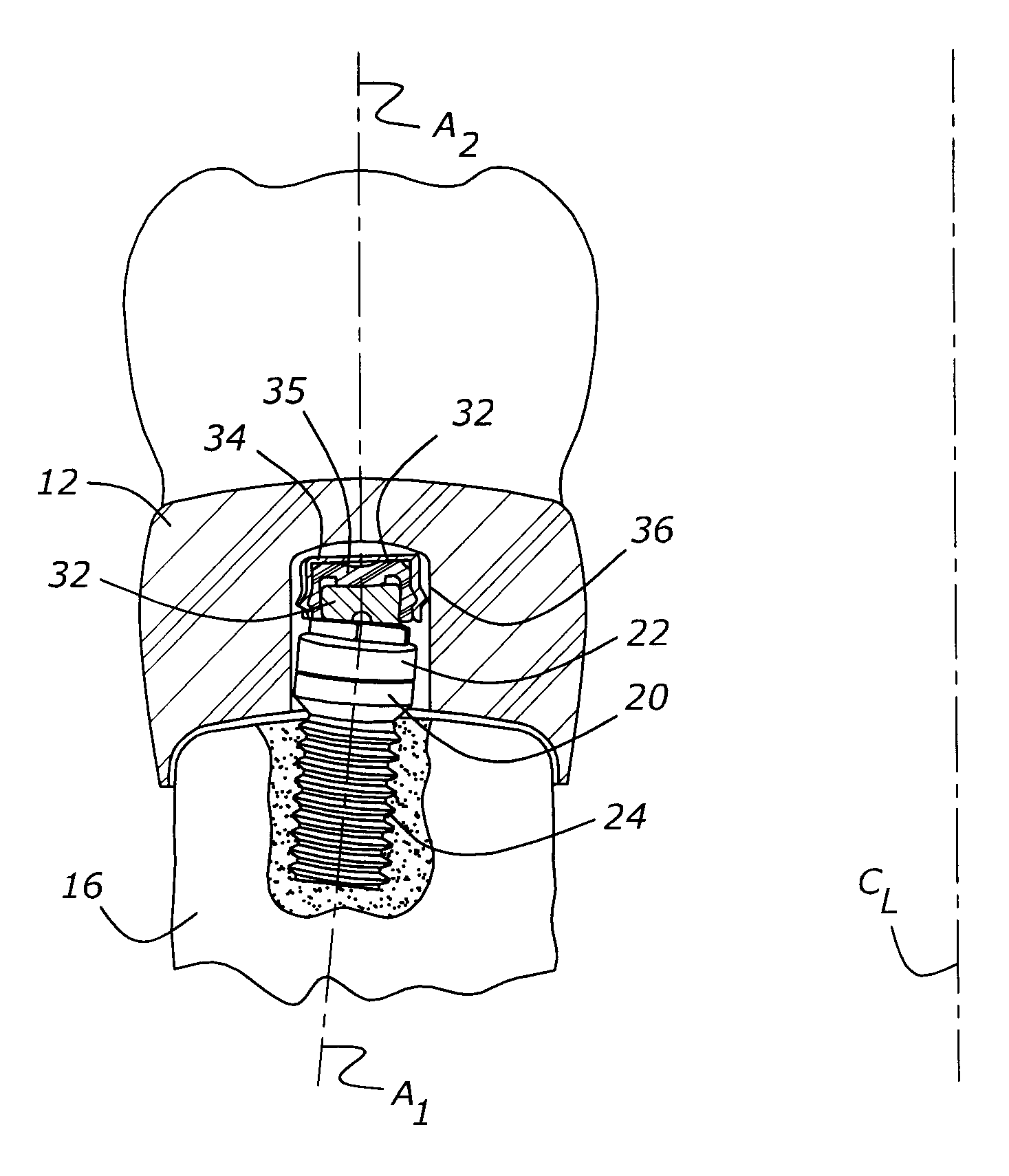
[0028]As shown in FIG. 1, an implant-based dental restoration includes an implant, 20, which is shown as having been placed within a patient's mandible, 16. As shown in FIG. 1, the center axis, A1, of implant 20 is not parallel to the center line, or more precisely, the central plane, CL, of the patient's mandible. In other words, implant 20 is at an angle to an imaginary central plane, CL, extending through the patient's mouth. This lack of parallelism is not desirable, and is typically corrected through the use of hardware further described herein. The dental restoration also includes an abutment base, 22, which is threaded into internal threads, 24, carried within implant 20. Abutment base 22 provides a mounting location for a geometric compensator 32, which corrects for the angular mismatch between axis A1 of implant 20 and center line or plane CL of the patient's mouth. Geometric compensator 32 allows the axis, A2, of a pressure sensitive fastening, 36, which is attached to geo...


PUM


Abstract

An abutment analog for fabricating an implant-based dental restoration includes an abutment base which is fixed within a patient's mouth in an angularly indexed fashion. After an impression is made, an implant analog will be attached to the abutment analog, and the combined abutment analog and implant analog will be replaced within the impression. The resulting impression, including the abutment analog and attached implant analog, will be used to make a model of a patient's mouth structure, to permit fabrication of a dental restoration device in a laboratory.

Description

CROSS REFERENCE TO RELATED APPLICATIONS[0001]This application claims priority to Provisional Patent Applications No. 61 / 110,594 and 61 / 110,596 both filed Nov. 2, 2008, the entire disclosures of which are hereby incorporated by reference and relied upon.BACKGROUND OF THE INVENTION[0002]1. Field of the Invention[0003]The present invention relates to a method and apparatus for constructing a dental restoration which is retained within the mouth of a patient through the use of implanted anchors.[0004]2. Related Art[0005]The techniques and hardware used for implant dentistry continue to develop steadily. In general, the process of providing dentition based upon implants begins with a visit by a patient to a dentist or oral surgeon, who places one or more implants within the desired structure, such as a mandible. Once the implants have become integrated with the patient's bony matrix, the patient visits his or her dentist, wherein the process of constructing the restoration device begins....

Claims


Application Information

Patent Timeline
IPC IPC(8): A61C8/00A61C5/77
CPCA61C8/0001
Inventor CHAPEL, TIMOTHY DOW
Owner CHAPEL TIMOTHY DOW
Why Eureka
Try Eureka