Elastic hollow particles for annular pressure buildup mitigation

Inactive Publication Date: 2010-05-06
BP CORP NORTH AMERICA INC
View PDF12 Cites 25 Cited by
  • Summary
  • Abstract
  • Description
  • Claims
  • Application Information

AI Technical Summary

Benefits of technology

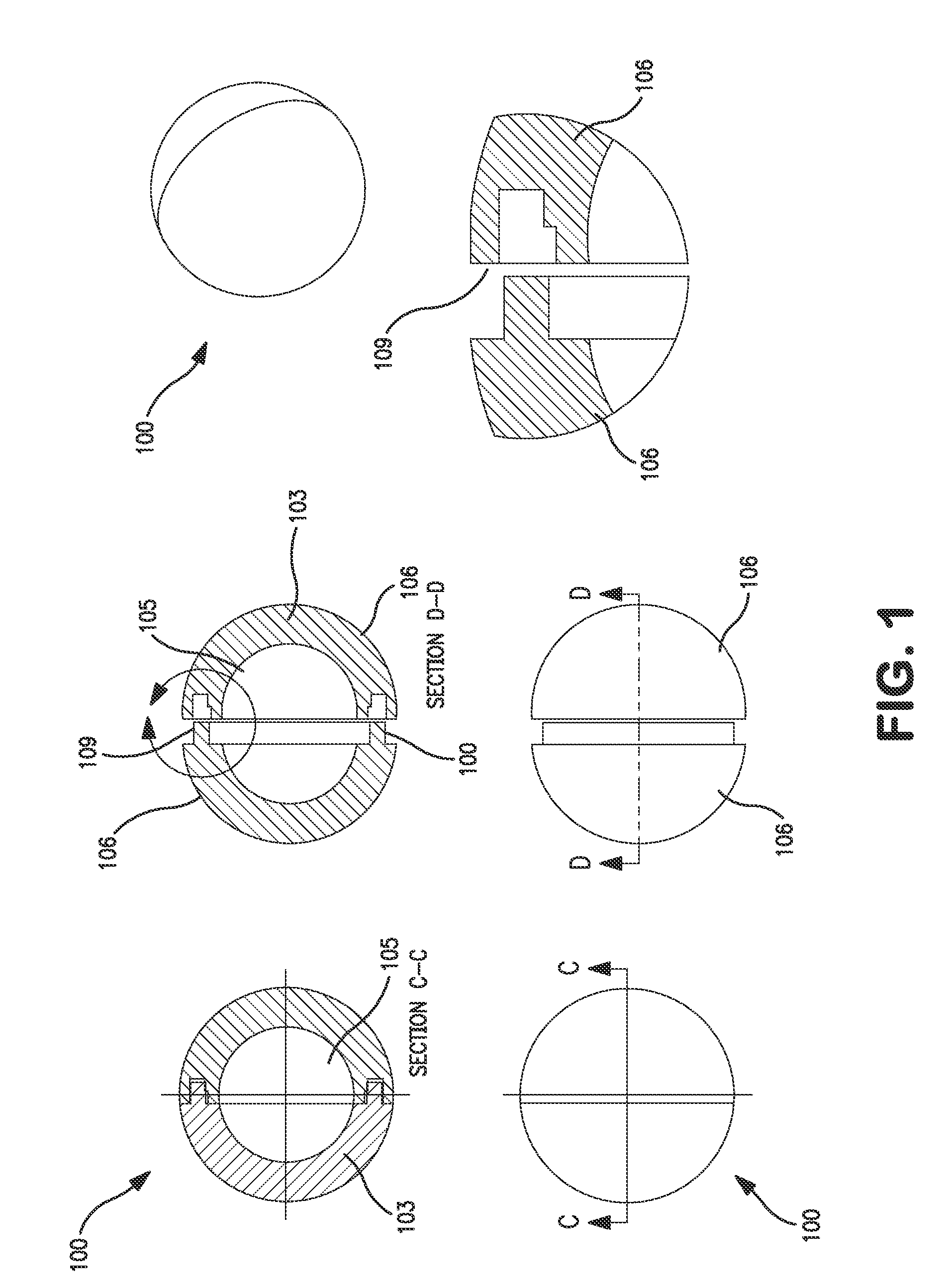
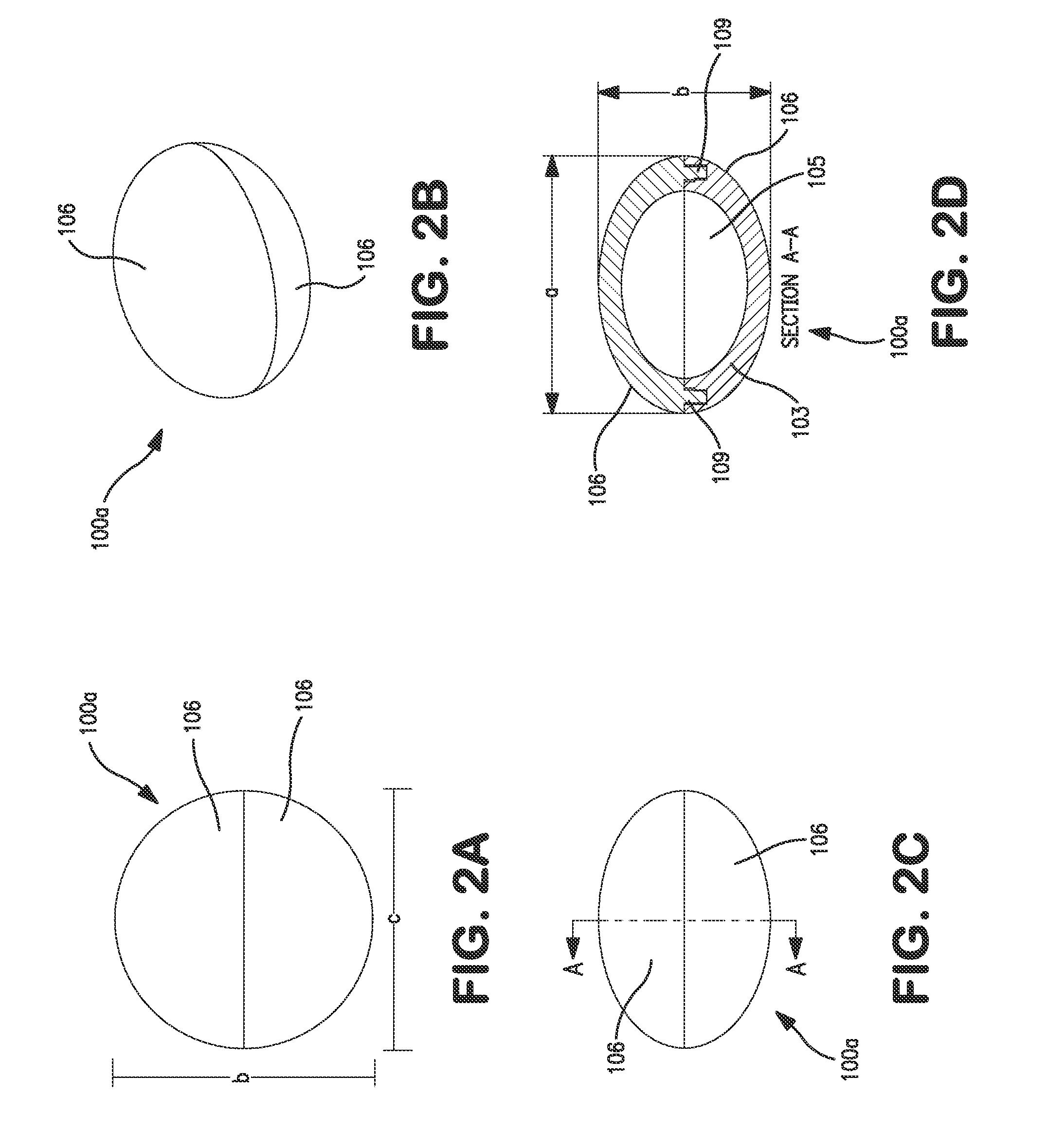
[0011]The concept involves placing within the annulus, hollow particles that possess material and geometric properties such that the hollow particles buckle at or near a defined pressure. Buckling of the particles increases the available volume within the annulus, thereby decreasing t

Problems solved by technology

As the oil and gas pass through the wellbore, heat may be passed from such fluids through the casing and into the annular space, which typically results in expansion of any fluids in the annular space.
Annular pressure build-up (APB) is a potentially dangerous condition in wells caused by a temperature driven increase in pressure within the annuli formed by downhole strings.
A significant increase in pressure within the annuli may have adverse consequences such as rupture of the casing wall o

Method used


Image

  • Elastic hollow particles for annular pressure buildup mitigation
  • Elastic hollow particles for annular pressure buildup mitigation
  • Elastic hollow particles for annular pressure buildup mitigation

Examples


Example

EXAMPLE 1

[0040]A variety of industries and materials suppliers were surveyed to locate readily available, off-the-shelf hollow polymer particles. The search criteria were limited to the following: the particles had to be hollow and made of plastic or rubber, with an outside diameter of no more than 10 mm. While the downhole operating requirements are much more stringent, these relatively simple criteria allowed acquisition of particles that could serve as potential concept demonstrators.

[0041]After considering a variety of experimental techniques for applying elevated pressures on the order of 15,000 psi and measuring changes in volume demonstrated by the elastic hollow particles, a High Pressure Pump Model 68-5.75-15 from High Pressure Equipment (HiP) was acquired. This device is a manual screw-driven pressure generator that is capable of applying pressures up to 15,000 psi in a small cylindrical chamber approximately 16 inches long and 11 / 16 inch in diameter. For each experiment,...

Example

EXAMPLE 2

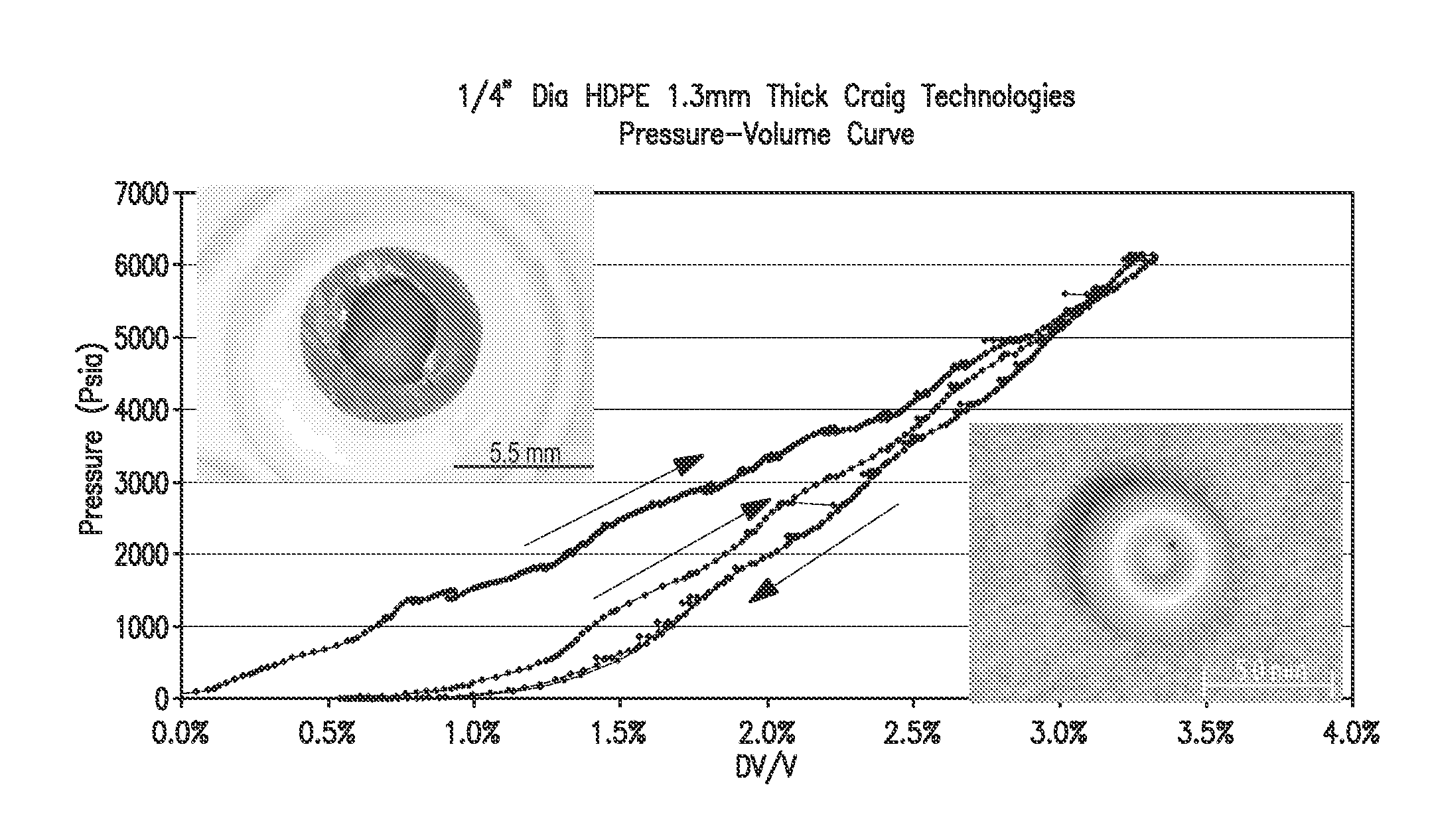
[0042]This experiment involved two pressure cycles up to 10,000 psi of an 11.6% mixture in volume of a sample of polypropylene hollow particles (Sample 1) and water. The elastic hollow particles used for this experiment had an outside diameter of 2.5 mm and a variable size cavity. Microscopic exploration revealed that the size of the cavity was minimal. As a result, the pressure-volume curve (as shown in FIG. 3) was very similar to that obtained in an experiment involving only the compression of water and residual air.

Example

EXAMPLE 3

[0043]This experiment involved two pressure cycles of a 5.6% mixture in volume of another sample of polypropylene elastic hollow particles (Sample 2) and water. Results are shown in FIG. 4. The polypropylene elastic hollow particles had a 10 mm diameter and a 1 mm wall thickness. The sound of the elastic hollow particles collapsing could be heard under the increasing pressure. As seen in the pressure-volume response, every collapsed particle provided additional volume and relieved the pressure in the chamber. Most of the elastic hollow particles, with the exception of two, failed close to 2,000 psi. The failure mode representative of all ten elastic hollow particles is shown in FIG. 3.

[0044]The maximum pressure did not significantly exceed 2,000 psi until collapse of the final particle, which occurred at about 6.5% change in volume. This location on the plot is about 5% change in volume above the point at which the pressure first began to depart from 0 psi (1.5%). This valu...


PUM


Abstract

The concept involves placing within the annulus, hollow particles that possess material and geometric properties such that the hollow particles buckle at or near a defined pressure. Buckling of the particles increases the available volume within the annulus, thereby decreasing the annular pressure. The elastic hollow particles are designed such that they buckle in a sufficiently elastic manner to allow them to rebound towards their original shape as the pressure decreases. The rebounded particles then remain available to mitigate subsequent instances of APB.

Description

CROSS-REFERENCE TO RELATED APPLICATIONS[0001]This application claims the benefit of U.S. Provisional Application No. 61 / 110,175, filed Oct. 31, 2008, which is hereby incorporated by reference in its entirety for all purposes.STATEMENT REGARDING FEDERALLY SPONSORED RESEARCH OR DEVELOPMENT[0002]Not applicable.BACKGROUND[0003]1. Field of the Invention[0004]This invention relates generally to the field of drilling. More specifically, the invention relates to compositions and methods for annular pressure buildup mitigation.[0005]2. Background of the Invention[0006]Natural resources such as oil or gas residing in a subterranean formation are recovered by drilling a well into the formation. The subterranean formation is usually isolated from other formations using a technique known as well cementing. In particular, a wellbore is typically drilled down to the subterranean formation while circulating a drilling fluid through the wellbore. After the drilling is terminated, a string of pipe (e...

Claims


Application Information

Patent Timeline
IPC IPC(8): C09K8/68
CPCE21B33/13E21B41/00
Inventor SHEPHERD, JAMES E.RAKOW, JOSEPH F.PATTILLO, II, PHILLIP DAVID
Owner BP CORP NORTH AMERICA INC
Why Eureka
Try Eureka