Prophylactic Pancreatic Stent

a pancreatic stent and stent technology, applied in the field of stents, can solve the problems of affecting the treatment effect of patients, so as to facilitate the advancement into the patient and reduce the diameter

Inactive Publication Date: 2010-05-06
WILSONCOOK MEDICAL
View PDF4 Cites 40 Cited by
  • Summary
  • Abstract
  • Description
  • Claims
  • Application Information

AI Technical Summary

Benefits of technology

This patent describes a type of stent that can be used to keep open a duct in our body. It consists of a thin tube made up of two parts: a main part and a removable top part. When it's placed inside us, the top part expands out to make sure no other objects enter the duct without permission. This helps to prevent damage or injury during procedures where we may want to use instruments within the duct.

Problems solved by technology

This patent describes a problem where there is a risk of injury during minimal invasive medical procedures in the biliary system, particularly if the procedure involves accessing the pancreatic duct. There is also a possibility of complications related to incorrect placement of wires and catheters which could result in inflammation and even permanent damages to the pancreas. To address this issue, the patent proposes a temporary stent that can protect the pancreatic duct from these risks while still allowing effective treatment of the desired area.

Method used


Image

  • Prophylactic Pancreatic Stent
  • Prophylactic Pancreatic Stent
  • Prophylactic Pancreatic Stent

Examples


Embodiment Construction

[0024]The invention is described with reference to the drawings in which like elements are referred to by like numerals. The relationship and functioning of the various elements of this invention are better understood by the following detailed description. However, the embodiments of this invention are not limited to the embodiments illustrated in the drawings. It should be understood that the drawings are not to scale, and in certain instances details have been omitted which are not necessary for an understanding of the present invention, such as conventional fabrication and assembly.

[0025]As used in the specification, the terms proximal and distal should be understood as being in the terms of a physician delivering the stent to a patient. Hence the term “distal” means the portion of the stent that is farthest from the physician and the term “proximal” means the portion of the stent that is nearest to the physician.

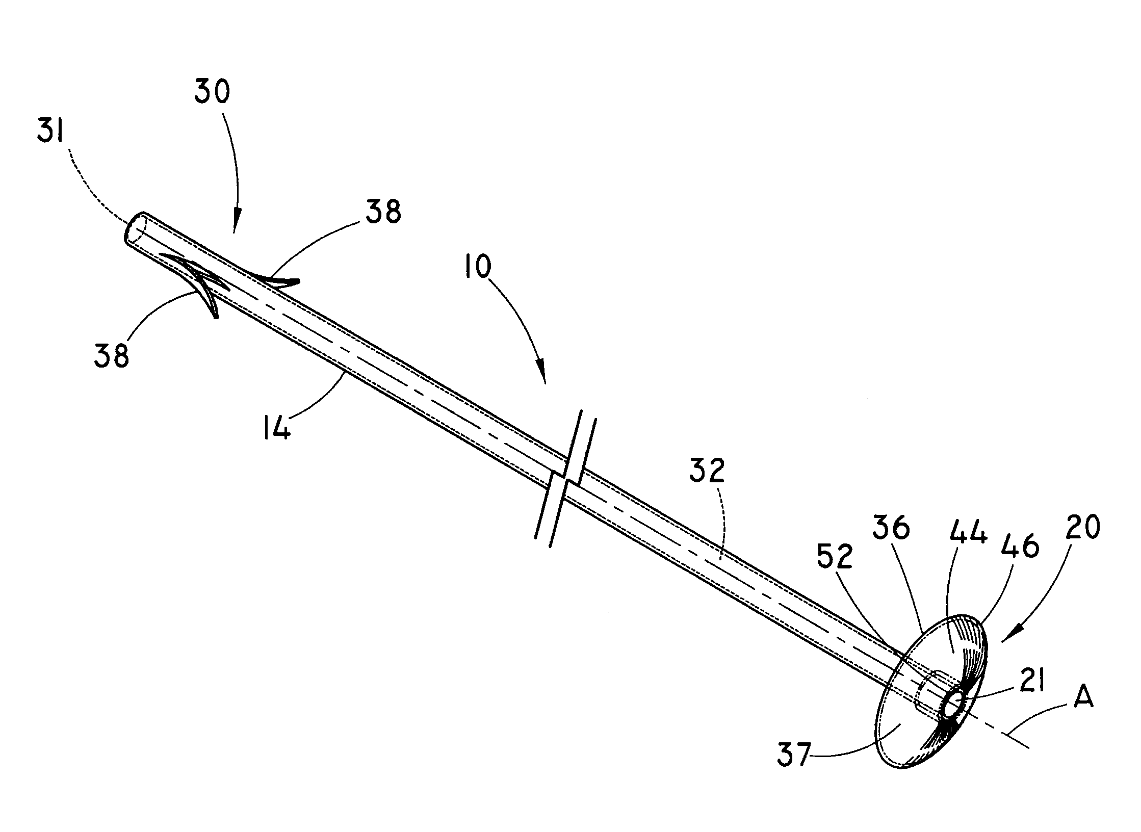
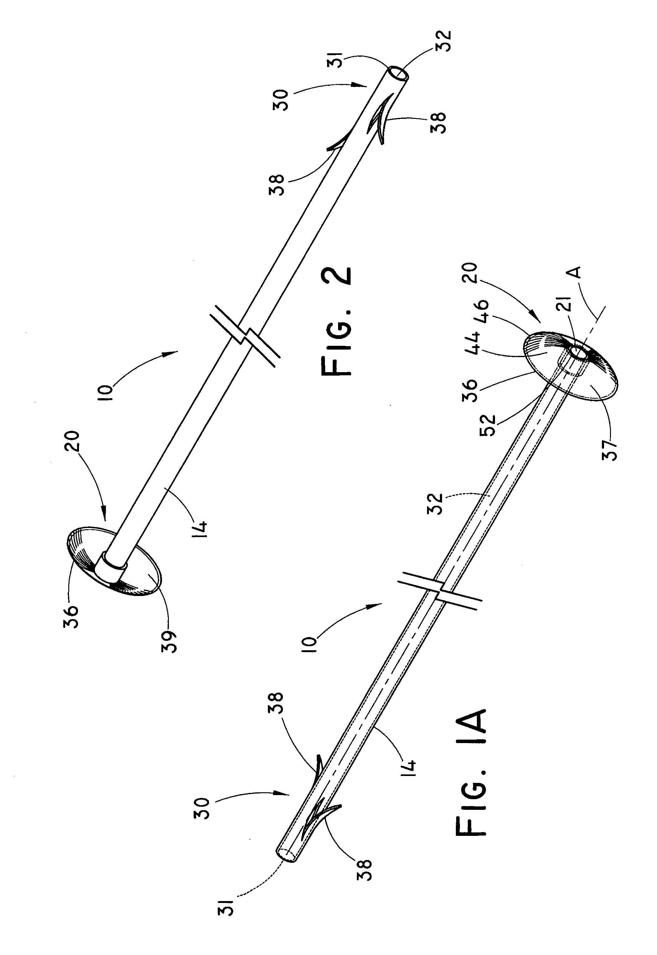
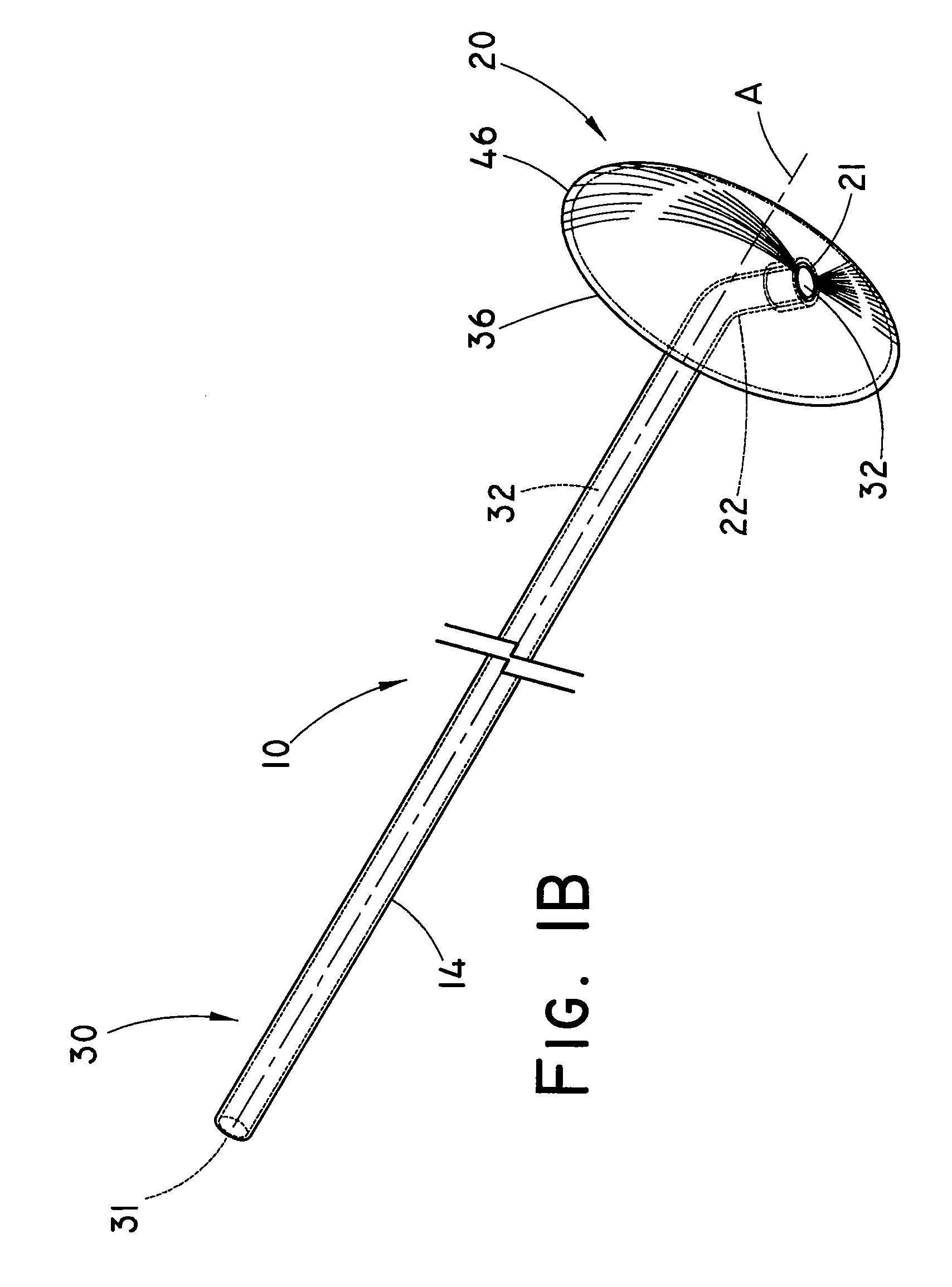
[0026]FIGS. 1A, 1B and 2 illustrate a stent 10 in accordance with e...


PUM


Abstract

A stent and a method for implanting a stent for prophylactically protecting a duct are provided. The stent includes a non-expandable, generally tubular body having a proximal portion and a distal portion, a lumen extending through at least a portion of the body, a distal opening in the distal portion in fluid communication with the lumen and a proximal opening in the proximal portion in fluid communication with the lumen. The stent further includes a cap portion operably connected to the proximal portion of the body, the cap portion is movable between a non-expanded configuration and an expanded configuration. The non-expanded configuration has a reduced diameter to facilitate advancement into the patient and the expanded configuration has an expanded diameter configured to protect an opening of the internal bodily duct so as to prevent an unintentional entry of an elongate medical device through the opening and into the passageway of the internal bodily duct.

Description


Claims


Application Information

Patent Timeline
Owner WILSONCOOK MEDICAL
Why Eureka
Try Eureka