Such shock-absorbers are typically hydraulic / gas or friction and are “always on”—meaning that even relatively slow movements of the steering mechanism add to the force required to steer the vehicle.
This means that there is always some incremental added force required by the driver to steer except when going in a straight or nearly straight line, or when making (relatively) long sweeping arcs with the vehicle.
This force is either provided by the driver's muscles (which fatigues the driver) or by the
power steering apparatus (which wastes
engine power).
This action / reaction
scenario bleeds-off speed and also causes the vehicle to try to follow a less optimal course—and is therefore undesirable in a competitive situation and often poses a safety
threat as well.
However, turning the Wheel / Tire to the right even a small amount more than absolutely necessary to negotiate the intended path actually increases the geometric profile of
impact of the steered Wheel / Tire causing an even more exaggerated action / reaction.
All of the above scrub-off speed and require even more time to negotiate the intended path.
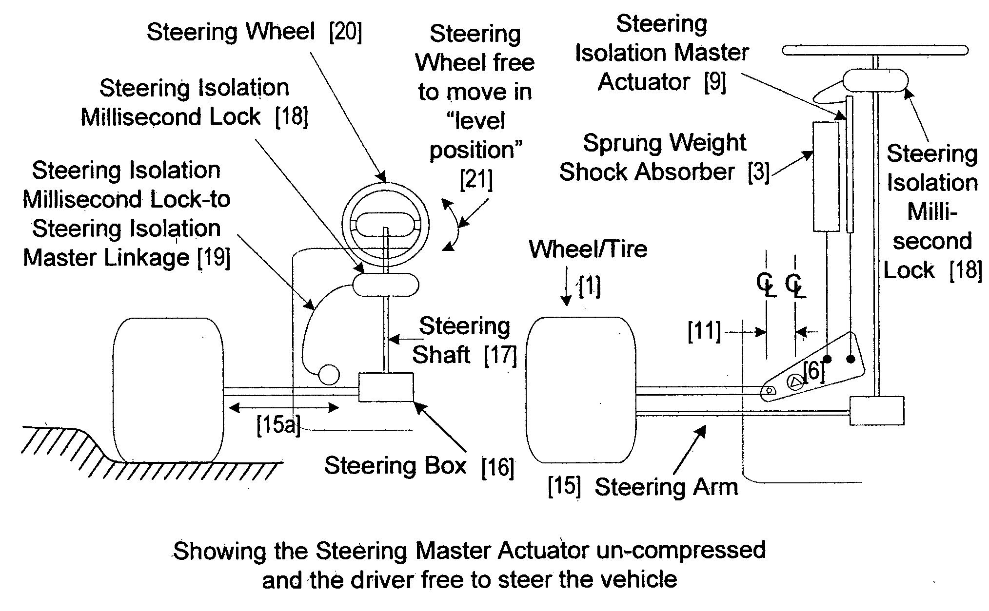
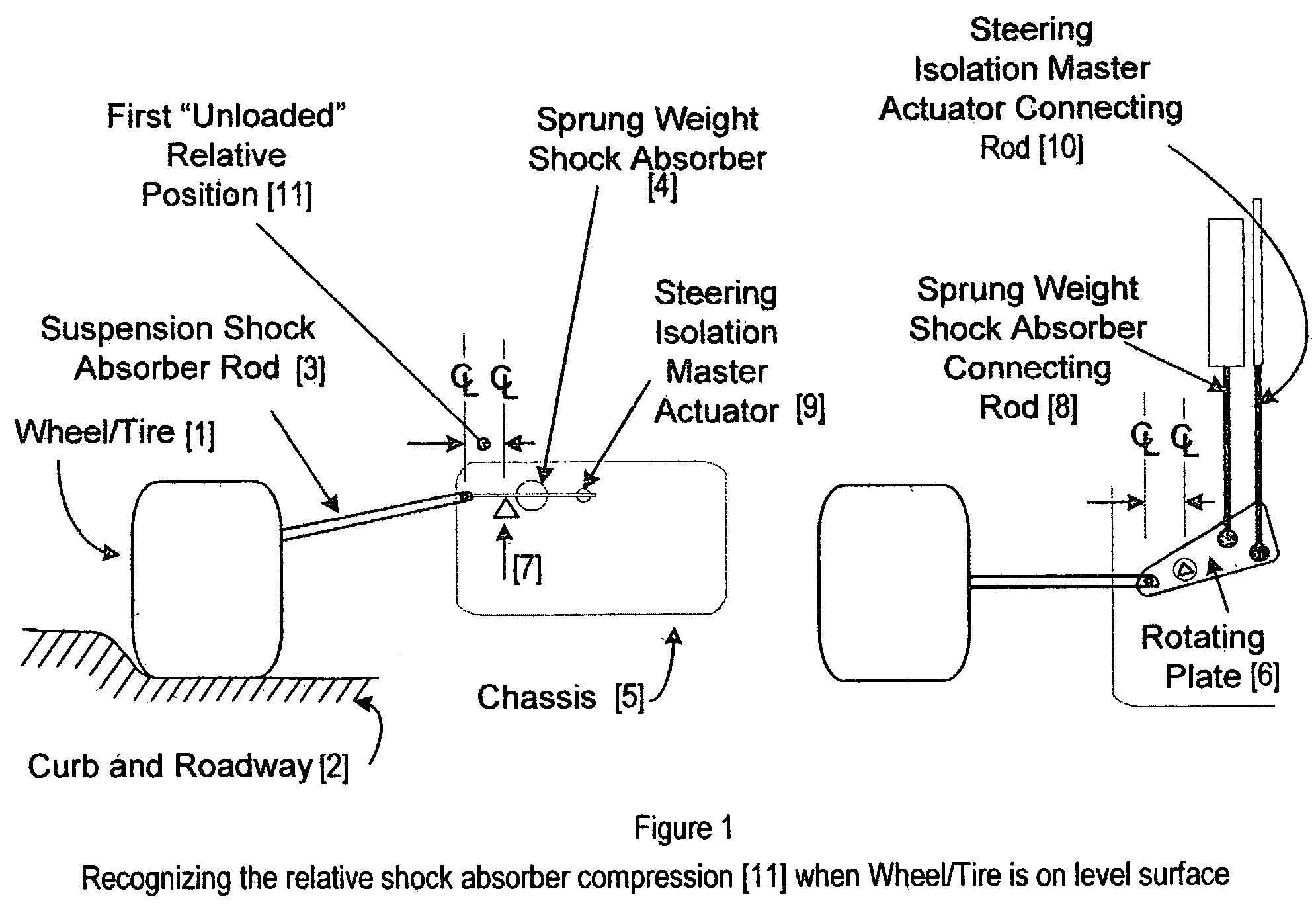
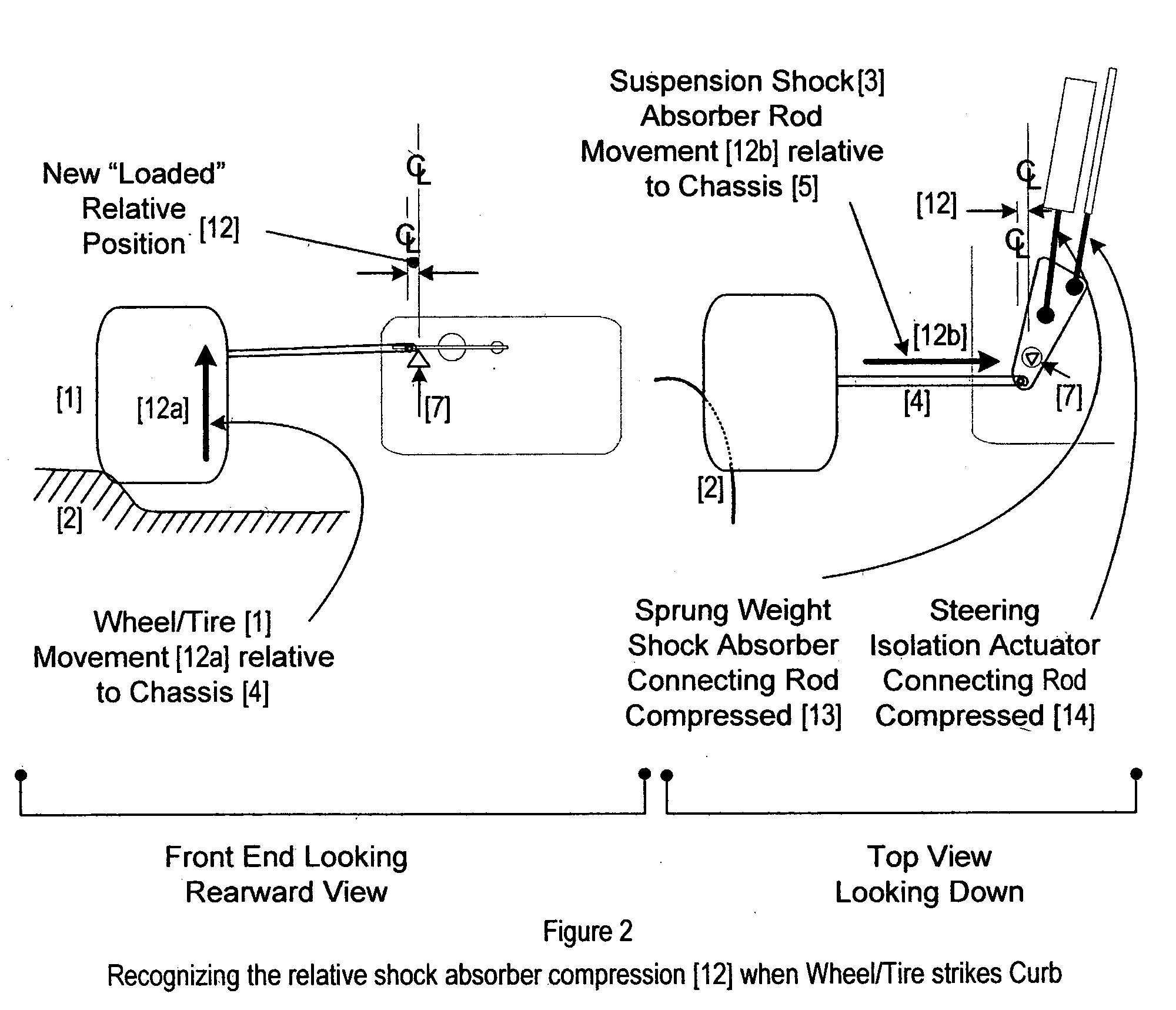
Therefore, a second un-served need exists for a steering shock-absorption / shock isolation method that will react to the
impact fast enough to “freeze the steering apparatus” for a few milliseconds such that the Wheel / Tire is not allowed to present said increasingly flat surface to the face of the Curb which typically results in “more air time” with attendant increased movement opposite of the driver's intention owing to the lack of tire contact with the racing surface.
Further, a third un-served need exists for a steering shock-absorption / shock isolation method that will react to the
impact fast enough to “freeze the steering apparatus” for a few milliseconds such that the Wheel / Tire does not present an increasingly flat surface to the face of the Curb (when the Wheel / Tire strikes the Curb, the Wheel / Tire is forced to turn into the Curb while the driver wishes to go in the direction originally directed by the
Steering Wheel) and which is not “always on” (as described above, with attendant loss of power from the engine and additional physical effort from the driver) but rather instant-on, instant-off.
Further, said method must be “instant-on” and “instant-off” or the driver will not thereafter be able to steer the vehicle owing to the steering being effectively locked.
Existing solutions embody a reduction of force transmitted to the driver, but no existing solution virtually isolates the driver from those forces.
The driver is not effectively isolated from the shock and reactive movement causing un-necessary skeletal strain in the driver's hands, wrists, and neck—even to the point of breaking.ii.
Great muscular effort is required by the driver to not allow the Steering Wheel to be wrested from his grasp in high-shock situations.iii.
The optimal course of direction of the vehicle is seriously compromised.vi.
Striking an un-anticipated object in the path of the vehicle may cause the Steering Wheel to be completely and violently wrested from the driver's hands—especially in a
crash situation.ix.
Even when present steering damping systems are reacting relatively slowly, there is a latent drag on the power of the vehicle owing to the fact that the (power) steering must be active at all times comprising a constantly available latent power sufficient to dampen (but not isolate) the shock to a steered Wheel / Tire being transmitted to the driver.

