Estimation of propagation angles of seismic waves in geology with application to determination of propagation velocity and angle-domain imaging

a technology of propagation velocity and measurement angle, applied in the direction of scientific instruments, measurement devices, instruments, etc., can solve the problems of inaccurate propagation velocity value, incorrect position of surface data, and inability to accurately measure the propagation velocity. , to achieve the effect of accurate measurement of the true propagation velocity

Inactive Publication Date: 2010-05-06
SEIMAX TECH LP
View PDF19 Cites 51 Cited by
  • Summary
  • Abstract
  • Description
  • Claims
  • Application Information

AI Technical Summary

Benefits of technology

[0012]The invention solves the problem of obtaining an accurate measure of the true propagation velocity which can be enhanced by obtaining the propagat

Problems solved by technology

When the migration velocity is incorrect, migration will incorrectly position the surface data in depth.
However, the slant stack may itself introduce spurious artifacts.
The method computed inaccurate values of the propagation velocity of seismic waves in the presence of reflector dip and source-receiver off

Method used


Image

  • Estimation of propagation angles of seismic waves in geology with application to determination of propagation velocity and angle-domain imaging
  • Estimation of propagation angles of seismic waves in geology with application to determination of propagation velocity and angle-domain imaging
  • Estimation of propagation angles of seismic waves in geology with application to determination of propagation velocity and angle-domain imaging

Examples


Embodiment Construction

[0049]The following description includes the best mode of carrying out the invention. The detailed description illustrates the principles of the invention and should not be taken in a limiting sense. The scope of the invention is determined by reference to the claims. Each part (or step) is assigned its own part (or step) number throughout the specification and drawings. Because some flow charts don't fit in a single drawing sheet encircled capital letters (e.g., “L”) show how the flow charts connect (e.g., L connects the flowcharts of FIGS. 22 and 23). The punctuation mark ′ and apostrophe ' mean prime wherever they appear in the drawings and specification.

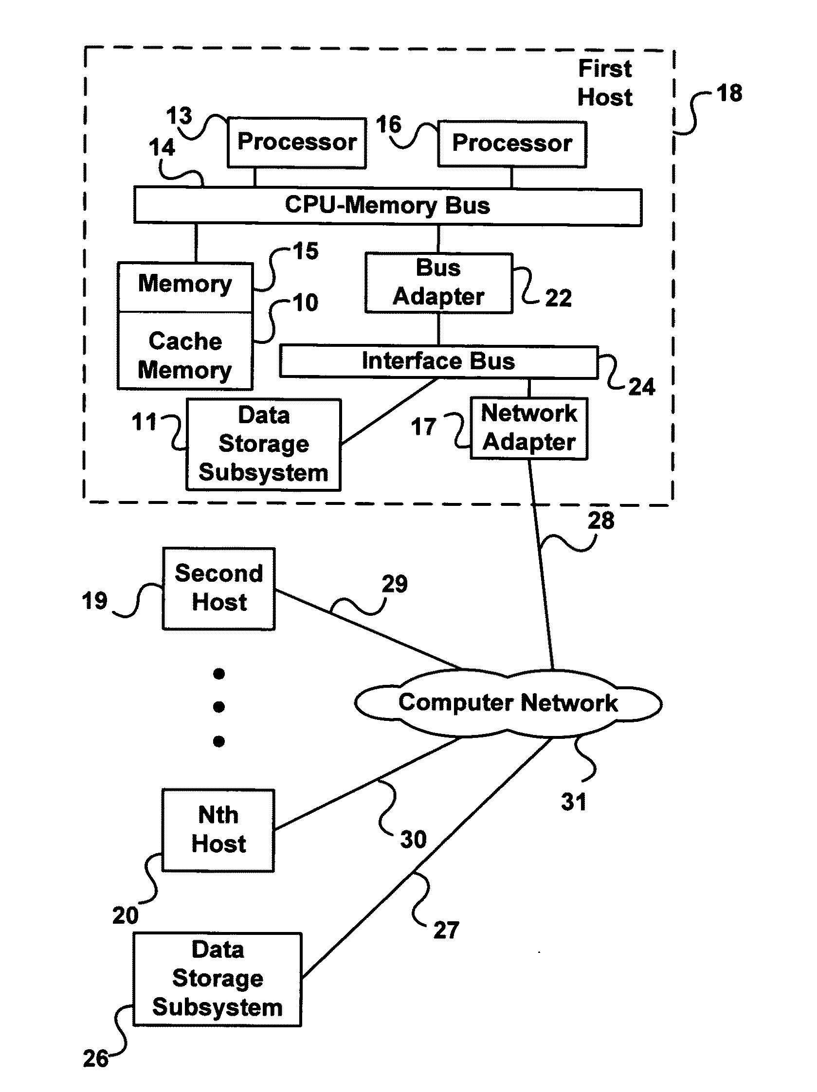
[0050]FIG. 1 illustrates a cluster of hosts that can execute the methods in software as described below. Each host is a computer that can communicate with data storage subsystems 11 and 26 (e.g., a disk array and / or solid state memory) and with each other. Hennessy and Patterson, Computer Architecture: A Quantitative Approach (20...


PUM


Abstract

The invention relates to methods and computer-readable medium to implement computing the propagation velocity of seismic waves in the earth. The invention computes the true propagation velocity of seismic waves in the earth, which is a condition of obtaining an accurate image of subsurface geology that can be used to prospect for oil and gas deposits. In an embodiment, the method of computing the propagation velocity of seismic waves in earth, includes providing an estimate of the propagation velocity, generating a time shift gather using a depth migration at a plurality of locations of the earth, converting each of the time shift gathers to a semblance gather, transforming each semblance gather into a velocity gather whose energy peaks represent a root-mean-square average of the propagation velocity along the forward and backward path between earth's surface and a point of the subsurface geology, and converting the energy peaks to the propagation velocity.

Description

[0001]This application is a continuation-in-part of U.S. application Ser. No. 12 / 221,390, Methods and Computer-Readable Medium to Implement Computing the Propagation Velocity of Seismic Waves, filed on Aug. 1, 2008, which is incorporated by reference herein.BACKGROUND[0002]The invention relates to determining propagation angles of reflected seismic waves in complex geology. The invention also relates to using measured propagation angles to enhance determination of propagation velocity and to effect angle-domain imaging of reflected seismic waves to produce an accurate image of earth's geology.[0003]Knowledge of the propagation velocity of seismic waves is required to produce accurate images of underground geology to prospect for oil and gas with the reflection seismic method. The reflection seismic method deploys an array of sound sources (e.g., dynamite, air guns, and vibrating trucks) and receivers (e.g., seismometer or hydrophone) on or below earth's surface to construct an image...

Claims


Application Information

Patent Timeline
IPC IPC(8): G01V1/28G06F19/00
CPCG01V1/28G01V1/303G01V2210/51
Inventor HIGGINBOTHAM, JOSEPH H.BROWN, MORGAN P.MACESANU, COSMIN
Owner SEIMAX TECH LP
Why Eureka
Try Eureka