
Strut for lifting a roof element used to cover a swimming pool and installation method thereof

Inactive Publication Date: 2010-05-13
ABRISUD
View PDF10 Cites 0 Cited by
  • Summary
  • Abstract
  • Description
  • Claims
  • Application Information

AI Technical Summary

Benefits of technology

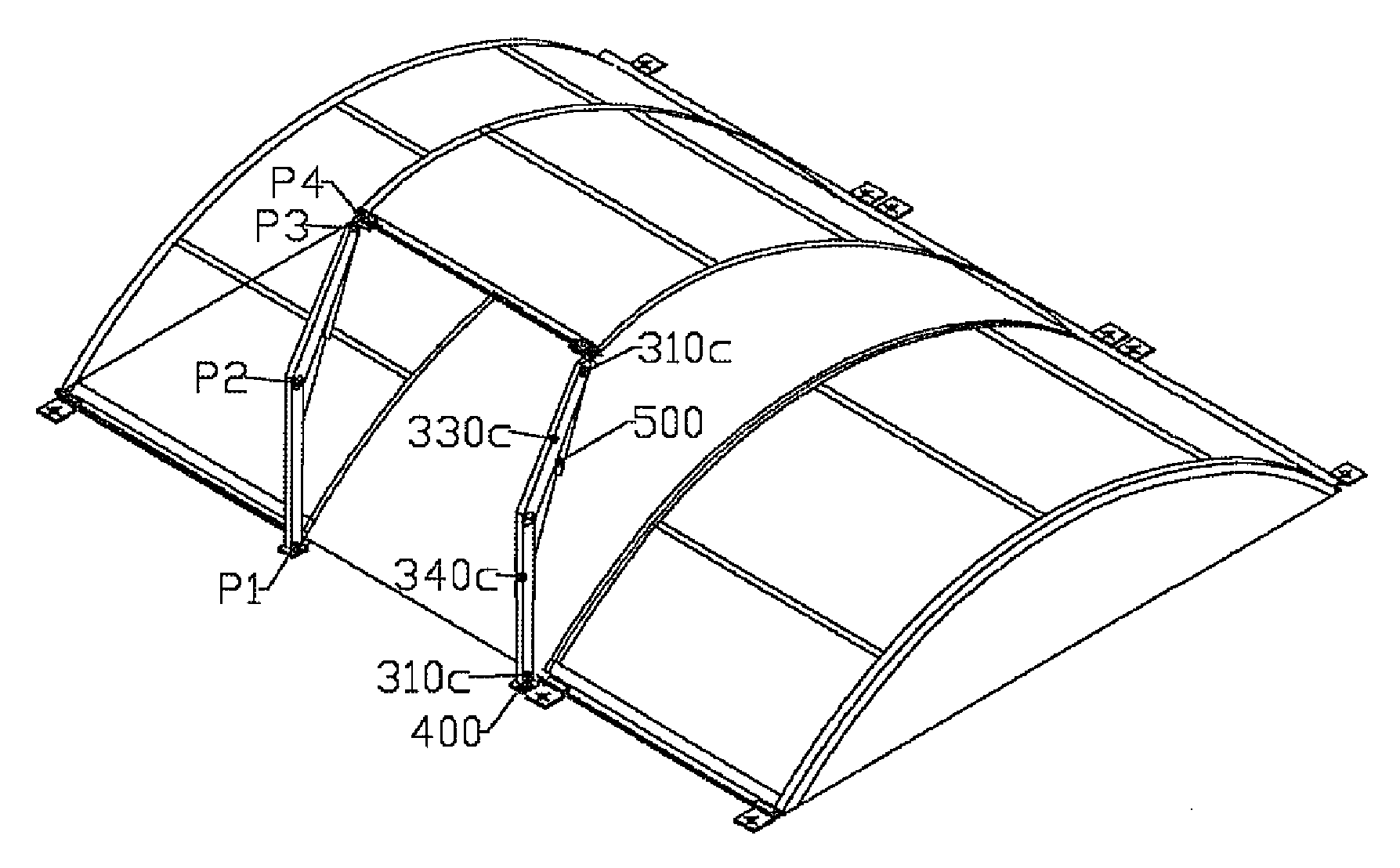
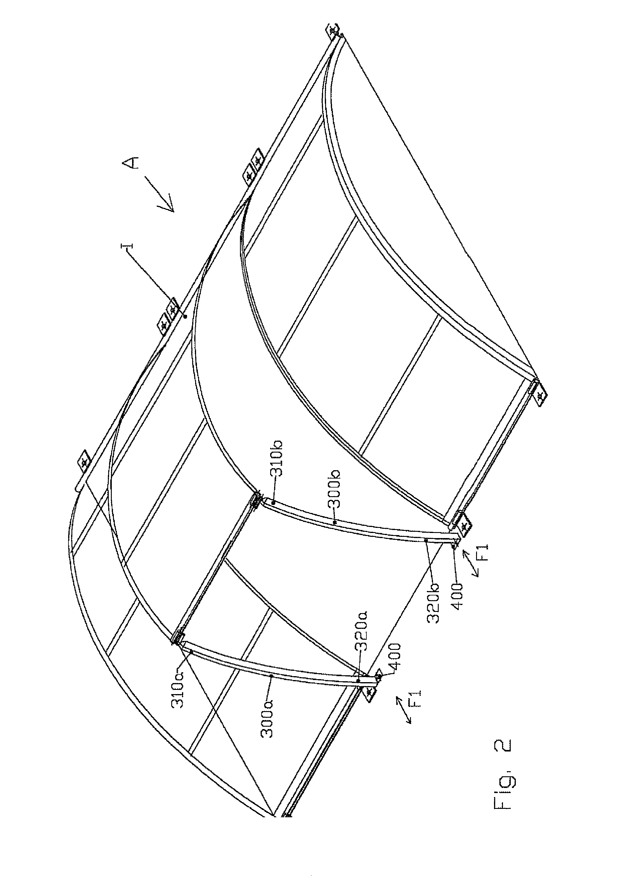
[0014]This research has resulted in the designing and in the carrying out of a strut for lifting or for maintaining in open position a roof element comprising a swimming pool shelter resting on the edges of a pool that it covers. According to the invention, this strut is remarkable in that it comprises a high end linked in articulation to the edge of a roof element and a low end connected to the ground, via a means of fastening, making it possible to vary the position of the point of linking of the low end of the strut in relation to the ground.
[0015]This characteristic is particularly advantageous in that it makes it possible to correct the inaccuracies in positioning fastening holes for fastening plates to the ground. Furthermore, it makes it possible to take into account any dimensional variations in the elements comprising the roof shelter. It also makes it possible to be able to use the same strut model for several dimensions or configurations of the roof elements. As such, for example for a telescopic or semi-sliding shelter, the same lifting strut can be used for the lifting of the fixed element as well as for the lifting of the mobile element, despite the differences in dimensions and in positions of the fastening points in relation to the edge of the roof element.
[0024]The implementation of the adjusting of the position of the low end of the strut is therefore carried out very simply and at a least cost.
[0025]The adjusting of the position of the low end of the strut has the advantage of being able to adjust in a certain configuration the inclination of the strut. As such according to a particular configuration of the invention, the strut is broken down into two foldable portions of which the deployment and the folding are accompanied by a jack, the point of articulation of the low end of the strut defined by the axis of said bearings being arranged higher than the point of articulation of the high end of the strut with the edge of the roof element. This configuration associated with the adjusting of the position of the fastening plate is going to make it possible to vary the angle of inclination of the folded strut towards the shelter since a position substantially inclined towards the shelter of the retracted strut has for great advantage of overcoming the problems of the untimely opening of the strut.
[0026]As such, the strut of the invention makes it possible to consider a method of installation that is remarkable in that it consists in fixing the high end of the strut to the edge of the roof element, in fixing the low end of the strut to the ground and in sliding the fastening lug of the strut towards the shelter in such a way that the folded strut can be inclined towards the shelter avoiding any risk of untimely opening.

Problems solved by technology

However, the dimensional tolerances of the roof elements, the expansion and the contraction of the latter as well as the positioning tolerances of the fastening holes of the fastening lugs, make for possible difficulty in implementing this maintaining in position by fastening lug.
These disadvantages are even more substantial when the fastening lug is used as a plate linked in articulation to a lifting strut and in particular to a foldable lifting strut associated with a jack accompanying the opening and damping the closing of the roof element.
In the opposite case, the following disadvantages can appear:the strut is placed in a horizontal position and forms an obstacle,the strut and therefore the roof element open untimely,the strut and therefore the roof element require additional effort for their opening,the struts of the same roof element do not have the same positioning,the struts of different roof elements do not have the same positioning and must therefore have different configurations.

Method used


Image

  • Strut for lifting a roof element used to cover a swimming pool and installation method thereof
  • Strut for lifting a roof element used to cover a swimming pool and installation method thereof
  • Strut for lifting a roof element used to cover a swimming pool and installation method thereof

Examples


Embodiment Construction

[0013]Using this established fact as a starting point, the applicant has carried out research aiming to solve the problem of positioning inaccuracy of the fastening points and articulation of the roof elements of a swimming pool shelter. Another objective of the research carried out by the applicant was to guarantee the proper positioning of the struts in order to guarantee their proper operation and to avoid the aforementioned disadvantages.

[0014]This research has resulted in the designing and in the carrying out of a strut for lifting or for maintaining in open position a roof element comprising a swimming pool shelter resting on the edges of a pool that it covers. According to the invention, this strut is remarkable in that it comprises a high end linked in articulation to the edge of a roof element and a low end connected to the ground, via a means of fastening, making it possible to vary the position of the point of linking of the low end of the strut in relation to the ground....


PUM


Abstract

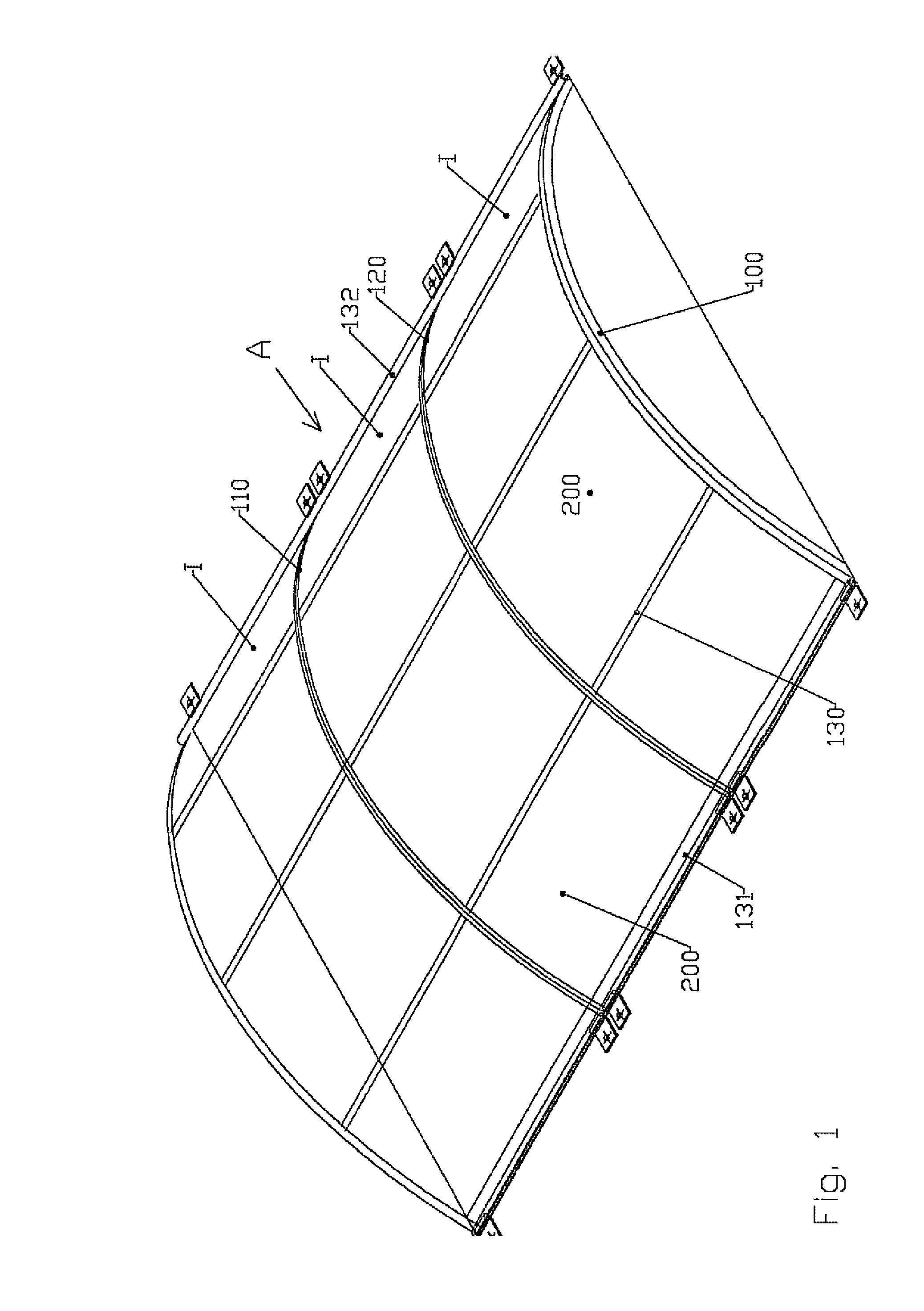
The invention relates to a strut (300a, 300b, 300c) for lifting a roof element (I) and / or maintaining same in the open position, said roof element forming a swimming pool enclosure (A) that rests on the edge of the pool. The invention is characterised in that it includes a high end (310a and 310b) hinged to the edge of a roof element (I) and a low end (320a and 320b) joined to the ground by a securing means (400), so that it is possible to vary the position of the point at which the low end (320a and 320b) of the strut (300a and 300b) is joined to the ground. The invention also relates to the method for installing one such strut. The invention is suitable for swimming pool enclosures.

Description

FIELD OF THE INVENTION[0001]This invention relates to the field of the means of fastening, articulating and lifting roof elements comprising swimming pool shelters.DESCRIPTION OF PRIOR ART[0002]It exists in prior art swimming pool shelters comprised of fixed, articulated, sliding telescopic roof elements, etc.[0003]The edges of these roof elements must be maintained in position using a fastening lug providing at one end the link with the roof element and at another end a link with the ground or with the curb by means of a bolt. Conventionally, these lugs assume the pivot articulations required for the half-open position of the roof elements.[0004]However, the dimensional tolerances of the roof elements, the expansion and the contraction of the latter as well as the positioning tolerances of the fastening holes of the fastening lugs, make for possible difficulty in implementing this maintaining in position by fastening lug.[0005]In addition, when the roof elements are not of the same...

Claims


Application Information

Patent Timeline
IPC IPC(8): E04H12/18E04B7/16E04B1/38
CPCE04H4/084
Inventor CHAPUS, CHARLES
Owner ABRISUD
Learn More