Integrated Combustor and Stage 1 Nozzle in a Gas Turbine and Method

a gas turbine and combustor technology, applied in the direction of efficient propulsion technologies, machines/engines, lighting and heating apparatus, etc., to achieve the effect of reducing flame length and flame length

Active Publication Date: 2010-05-13
GENERAL ELECTRIC CO
View PDF37 Cites 96 Cited by
  • Summary
  • Abstract
  • Description
  • Claims
  • Application Information

AI Technical Summary

Benefits of technology

[0005]In an exemplary embodiment, an integrated combustor and stage one nozzle in a gas turbine include a combustion chamber that receives premixed fuel and air from at least one fuel nozzle group at separate axial locations. The combustion chamber includes a liner and a transition piece that deliver hot combustion gas to the turbine. The stage one nozzle, the liner and the transition piece are integrated into a single part. At least one of the axial locations of the one or more fuel nozzle groups includes a plurality of small scale mixing devices that concentrate heat release and reduce flame length.
[0006]In another exemplary embodiment, the integrated combustor and stage one nozzle includes a combustion chamber that receives premixed fuel and air from at least one fuel nozzle group at separate axial locations. The combustion chamber includes a liner and a transition piece that deliver hot combustion gas to the turbine. At least one of the axial locations of the one or more fuel nozzle groups includes a plurality of small scale mixing devices that concentrate heat release and reduce flame length. The reduced flame length enables the stage one nozzle, the liner and the transition piece to be integrated into a single part.

Problems solved by technology

These leakages impact the emissions capability (i.e., NOx) of the combustor since large leakages will result in elevated combustion temperatures for the same turbine inlet temperature.

Method used


Image

  • Integrated Combustor and Stage 1 Nozzle in a Gas Turbine and Method
  • Integrated Combustor and Stage 1 Nozzle in a Gas Turbine and Method
  • Integrated Combustor and Stage 1 Nozzle in a Gas Turbine and Method

Examples


Embodiment Construction

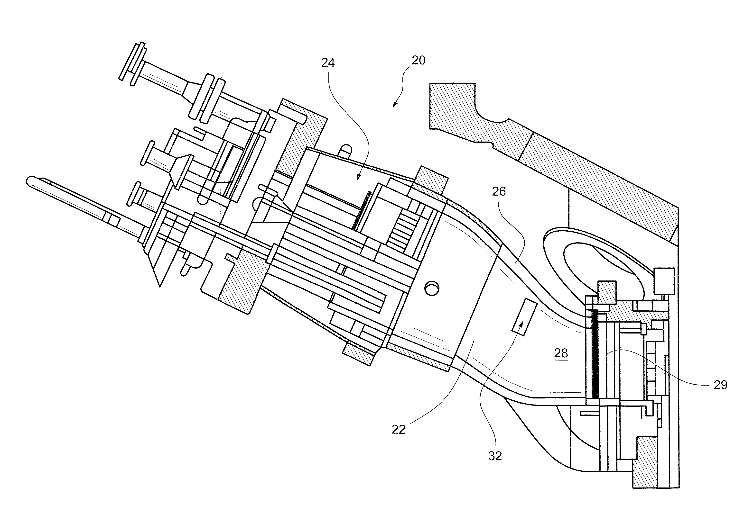
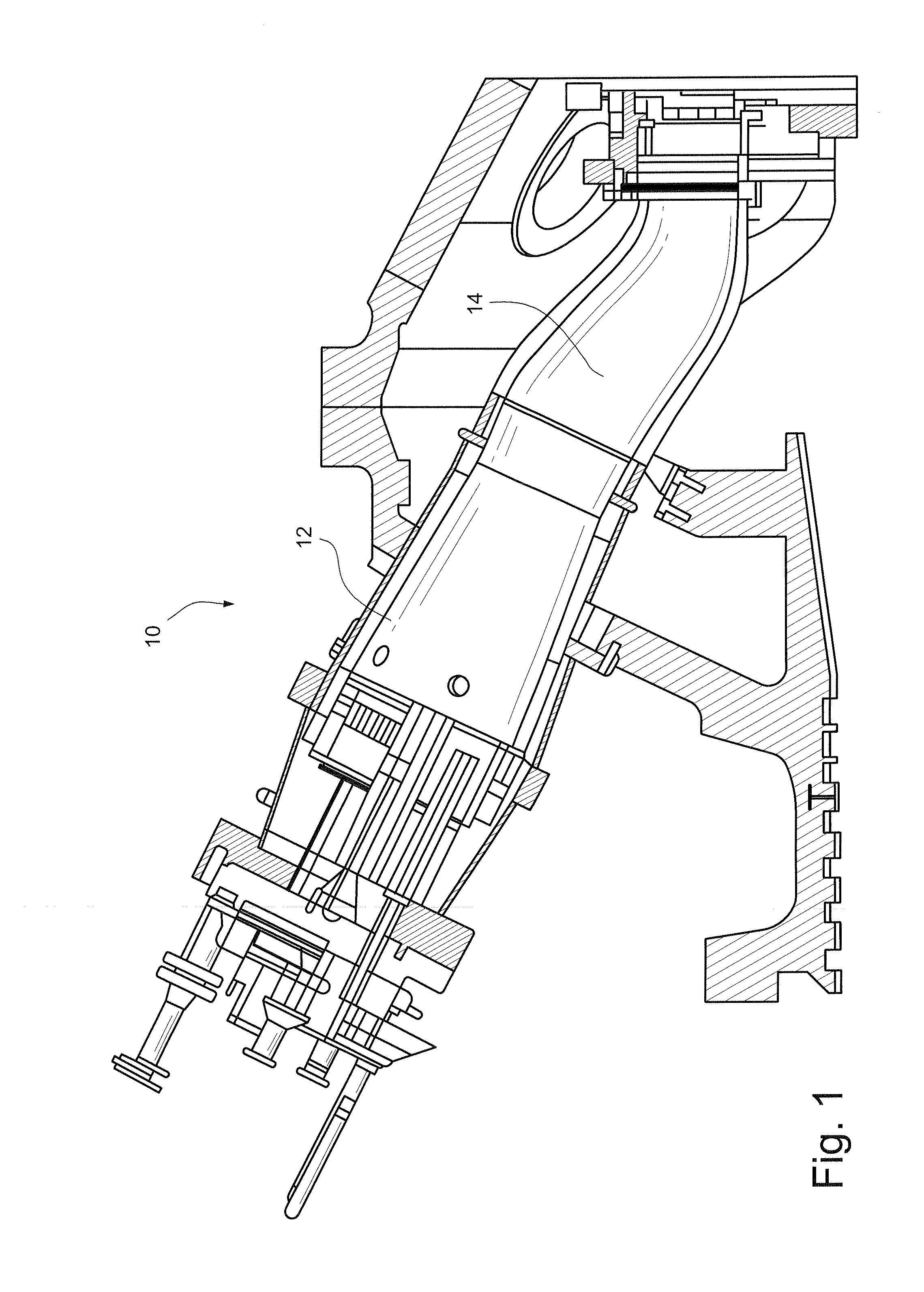
[0013]FIG. 1 illustrates a prior art combustor for a gas turbine, which includes a compressor, a plurality of combustors, and a turbine. Although not specifically shown, the turbine is drivingly connected to the compressor along a common axis. The compressor pressurizes inlet air, which is then reverse flowed to the combustor where it is used to cool the combustor and to provide air to the combustion process. The combustor 10 includes a liner 12 that defines a combustion zone and a transition piece 14 that connects the outlet end of the combustor with an inlet end of the turbine to deliver the hot products of combustion to the turbine. As noted, the interface between the combustion transition piece 14 and the turbine first stage nozzle requires the use of seals to minimize leakages into the gas path. In the described embodiments, it is proposed to integrate the stage 1 nozzle into the transition piece design.

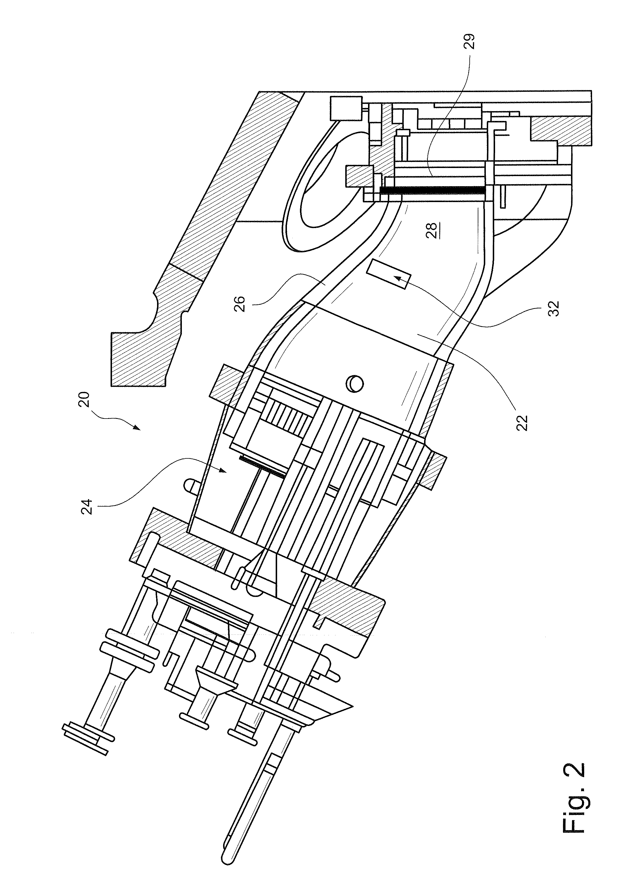
[0014]FIG. 2 is a cross-sectional view of the integrated combustor and stag...


PUM


Abstract

An integrated combustor and stage one nozzle in a gas turbine includes a combustion chamber that receives premixed fuel and air from at least one fuel nozzle group at separate axial locations. The combustion chamber includes a liner and a transition piece that deliver hot combustion gas to the turbine. The stage one nozzle, the liner and the transition piece are integrated into a single part. At least one of the axial locations of the one or more fuel nozzle groups includes a plurality of small scale mixing devices that concentrate heat release and reduce flame length.

Description

BACKGROUND OF THE INVENTION[0001]The invention relates to gas turbine combustors and, more particularly, an integrated combustor and stage 1 nozzle for a gas turbine.[0002]Gas turbine engines typically include a compressor section, a combustor section, and at least one turbine section. The compressor compresses air that is mixed with fuel and channeled to the combustor. The mixture is then ignited generating hot combustion gases. The combustion gases are channeled to the turbine, which extracts energy from the combustion gases for powering the compressor, as well as for producing useful work to power a load, such as an electrical generator.[0003]Typically, the combustion section is distinct and separate from the downstream turbine. In particular, for can-annular designs, these two components—combustor and turbine—meet at the interface of the combustion transition piece and the turbine first stage nozzle. This interface requires the use of seals to minimize leakages into the gas path...

Claims


Application Information

Patent Timeline
Patent Type & Authority Applications(United States)
IPC IPC(8): F23R3/42F02C7/22F02C3/14
CPCF01D9/023F01D9/041Y02T50/675F23R3/286F23R3/46F23R3/002Y02T50/60
Inventor DAVIS, JR., LEWIS BERKLEYZIMINSKY, WILLY STEVEMCMAHAN, KEVIN WESTONCHILA, RONALD JAMESMESHKOV, SERGEY ANATOLIEVICH
Owner GENERAL ELECTRIC CO
Why Eureka
Try Eureka