Fuel gas nozzle

a fuel gas nozzle and nozzle technology, applied in the direction of fuel supply regulation, combustion types, lighting and heating apparatuses, etc., can solve the problems of increasing the difficulty of controlling the flow rate of air, reducing the homogeneity of mixing of air and fuel gas, so as to achieve better combustion efficiency, reduce the size of the combustion chamber, and reduce the length of the flame inside the combustion chamber.

Active Publication Date: 2020-06-25
NAT CHUNG SHAN INST SCI & TECH
View PDF6 Cites 0 Cited by
  • Summary
  • Abstract
  • Description
  • Claims
  • Application Information

AI Technical Summary

Benefits of technology

[0005]Therefore, it is an objective of the present invention to provide a fuel gas nozzle used in a microturbine with an enhanced mixing effect of air and fuel gas for solving the aforementioned problems.
[0018]In summary, the present invention utilizes the intake pipe whose centerline is not intersected with the centerline of the second chamber to induce the vortex flow field of the air flowing into the mixing zone for mixing the air and the second fuel gas, so that the air and the second fuel gas can be completely mixed due to the vortex flow field of the air. Besides, the present invention further utilizes the distributor with the plurality of inclined blades for inducing the vortex flow field of the second fuel gas flowing into the mixing zone opposite to the vortex flow field of the air flowing into the mixing zone, so that the air and the second fuel gas can be completely mixed in a short time period due to the vortex flow field of the air and the vortex flow field of the second fuel gas. Since the air and the second fuel gas are completely mixed before being injected into a combustion chamber, a length of a flame inside the combustion chamber can be reduced effectively, so that a size of the combustion chamber can be also reduced accordingly. Furthermore, the air flows through the intake pipe into mixing zone along a single direction, and there is no other opening formed on the second chamber. Therefore, it prevents the second fuel gas inside the mixing zone from being blown out. Moreover, the present invention can adjust an air-fuel ratio, i.e, a ratio of the air to the second fuel gas, by controlling the flow rate of the air, according to different types of fuel gas, such as methane, propane, biogas and wood gas, with the flow control valve to achieve better combustion efficiency. Therefore, the fuel gas nozzle of the present invention is suitable for different microturbines in different applications, which facilitates promotion of green energy.

Problems solved by technology

However, the conventional flow design usually drives the air to flow along a single direction, i.e., a longitudinal direction of the mircoturbine, toward the fuel gas nozzle when the fuel gas nozzle is installed on the microturbine, so that the air hardly flows into the mixing chamber through the intake openings and the guiding plates located at a leeward side, which increases difficulty of controlling a flow rate of the air and brings a negative effect on inducing the vortex flow field of the air flowing into the mixing chamber, which reduces the homogeneity in mixing of the air and the fuel gas.
Furthermore, the fuel gas may be easily blown out from the mixing chamber through the intake openings by the air.
Therefore, a size of the mircoturbine cannot be reduced effectively due to the poor homogeneity in mixing of the air and the fuel gas.
However, when the air flows into the mixing chamber via the openings, the flow rate of the air cannot be adjusted according to different types of fuel gas, such as methane, propane, biogas and wood gas, due to a fixed size of the opening of the mixing chamber.

Method used


Image

  • Fuel gas nozzle
  • Fuel gas nozzle
  • Fuel gas nozzle

Examples


Embodiment Construction

[0026]In the following detailed description of the preferred embodiments, reference is made to the accompanying drawings which form a part hereof, and in which is shown by way of illustration, specific embodiments in which the invention may be practiced. In this regard, directional terminology, such as “top,”“bottom,”“front,”“back,” etc., is used with reference to the orientation of the Figure (s) being described. The components of the present invention can be positioned in a number of different orientations. As such, the directional terminology is used for purposes of illustration and is in no way limiting. Accordingly, the drawings and descriptions will be regarded as illustrative in nature and not as restrictive.

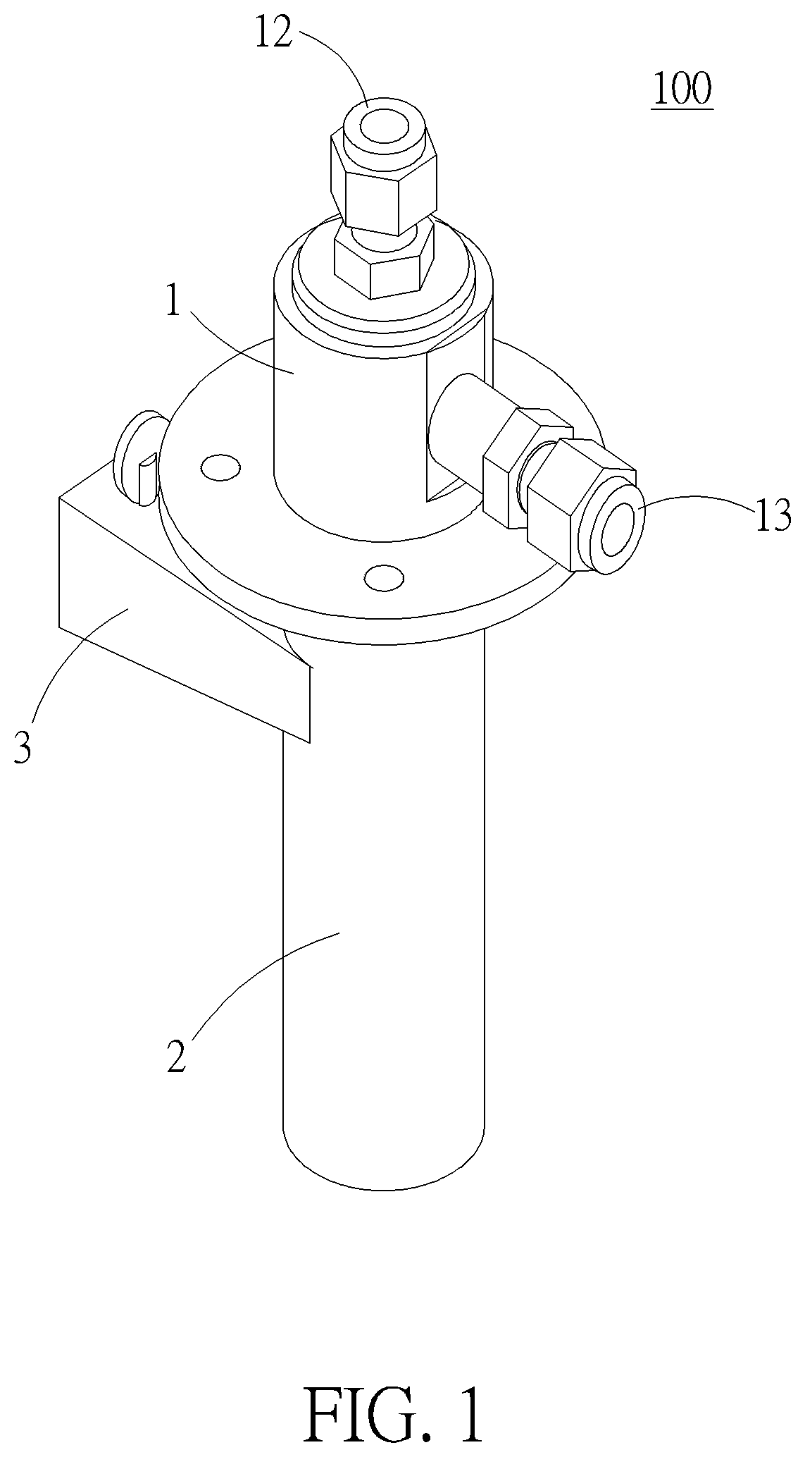
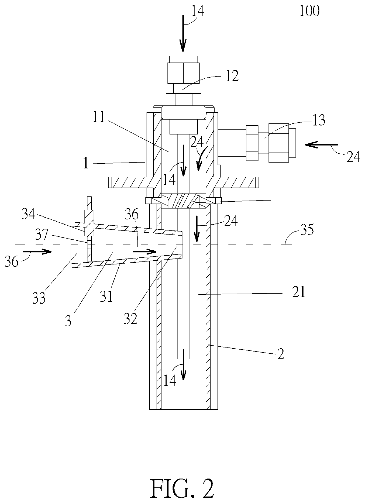
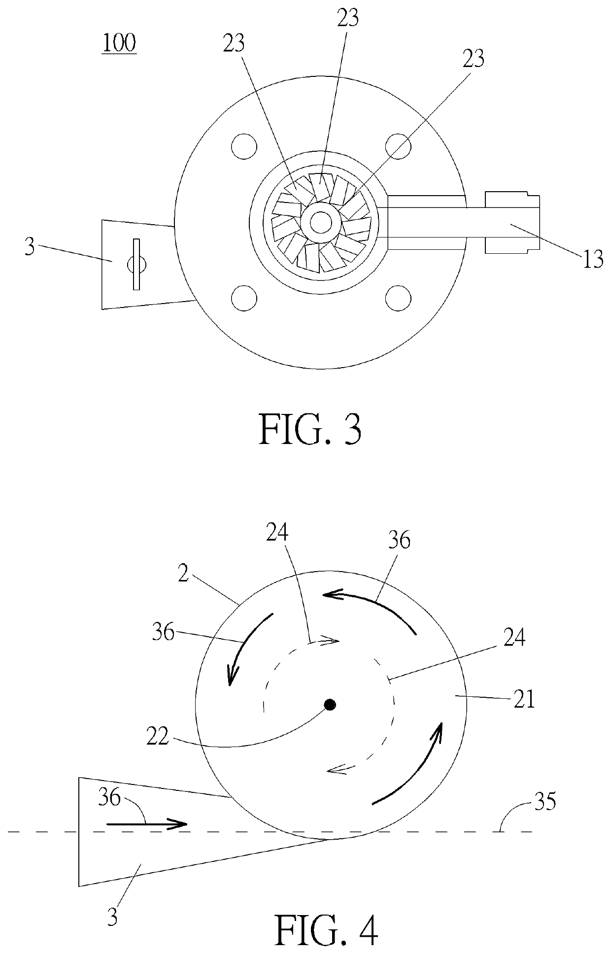
[0027]Please refer to FIG. 1 to FIG. 4. FIG. 1 is a schematic diagram of a fuel gas nozzle 100 according to a first embodiment of the present invention. FIG. 2 is a sectional diagram of the fuel gas nozzle 100 according to the first embodiment of the present invention. FI...


PUM


Abstract

A fuel gas nozzle used in a microturbine includes a first chamber, a second chamber connected to the first chamber, a pilot fuel gas pipe, a main fuel gas pipe and an intake pipe. An intake zone and a mixing zone are respectively formed in the first chamber and the second chamber and are communicated with each other. The pilot fuel gas pipe is for introducing a first fuel gas into a downstream of the second chamber. The main fuel gas pipe is for introducing a second fuel gas into the mixing zone via the intake zone. The intake pipe is for introducing an air into the mixing zone. A centerline of the intake pipe is not intersected with a centerline of the second chamber, so as to induce a vortex flow field of the air flowing into the mixing zone for mixing the air and the second fuel gas.

Description

BACKGROUND OF THE INVENTION1. Field of the Invention[0001]The present invention refers to a fuel gas nozzle used in a microturbine, in more detail, to a fuel gas nozzle used in a microturbine with an enhanced mixing effect of air and fuel gas.2. Description of the Prior Art[0002]A fuel gas nozzle is one of the accessory devices used in a microturbine and capable of introducing a mixture of air and fuel gas into a combustion chamber of the microturbine. A conventional fuel gas nozzle usually includes a mixing chamber, a plurality of intake openings arranged along a circumferential direction of the mixing chamber and a plurality of guiding plates located at the mixing chamber and adjacent to the corresponding plurality of intake openings. The intake openings introduce the air from surrounding environment into the mixing chamber, and guiding plates induce a vortex flow field of the air flowing into the mixing chamber to mix the air and the fuel gas. A flame size in the combustion chamb...

Claims


Application Information

Patent Timeline
Patent Type & Authority Applications(United States)
IPC IPC(8): F23R3/28F23N1/02F23R3/12F23K5/00
CPCF23N2235/16F23N2235/26F23R3/12F23R3/286F23N1/027F23K5/007F23N2239/04F23D14/24F23D2206/10F23R3/14F23R3/343F23R2900/00002F23R2900/03343F23R3/26
Inventor TSUEI, YUNG-MAOLEE, CHIH-CHUANCHIU, CHI-FANG
Owner NAT CHUNG SHAN INST SCI & TECH
Why Eureka
Try Eureka