
Engine startup control device for vehicle

a technology for engine startup and control device, which is applied in the direction of engine starter, motor/generator/converter stopper, dynamo-electric converter control, etc., can solve the problems of delay in engine rotation speed rise, limited battery charging or discharging, and risk of uncomfortable shock through the engine moun

Active Publication Date: 2010-05-13
TOYOTA JIDOSHA KK
View PDF9 Cites 69 Cited by
  • Summary
  • Abstract
  • Description
  • Claims
  • Application Information

AI Technical Summary

Benefits of technology

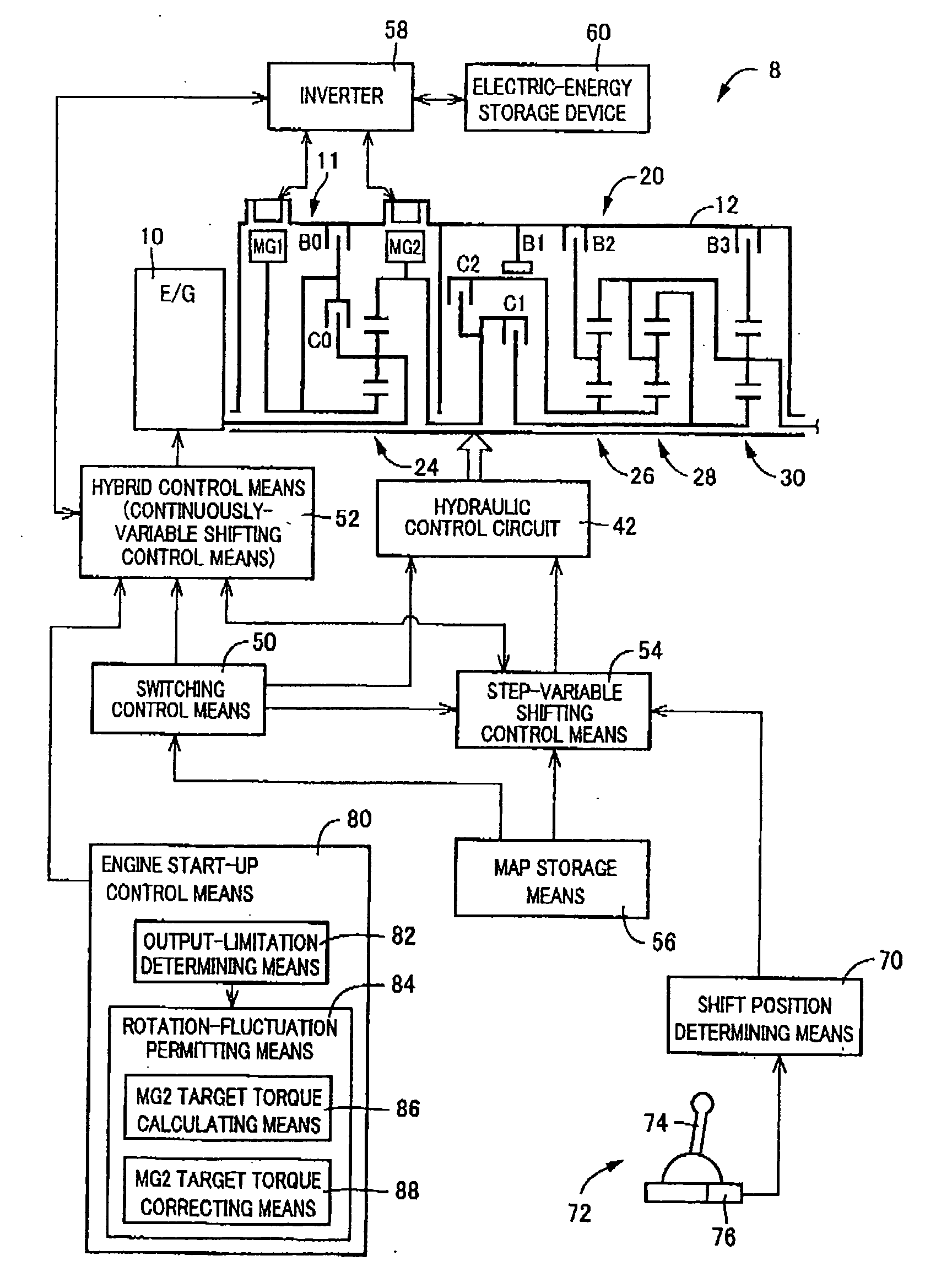
[0035]During the engine start-up with the output limitation of the first electric motor, performing the rotation-speed reference reactive-force control allows the reactive torque of the reactive-force control device to be controlled depending on the target rotation speed and sets the deviation permitting value so as to permit the rotation speed variation of the reactive-force receiving member. In determining such a deviation permit value, the same control as those of the fourth to sixth inventions can be applied. For instance, (a) the lower the output power of the first electric motor limited in the output limitation is, the greater the deviation permit value becomes; (b) during the engine start-up with the output limitation of the first electric motor, the variation amount of the rotation speed of the engine is detected to perform a control such that the greater the rotation speed variation is, the greater the deviation permit value will be; and (c) during the engine start-up with the output limitation of the first electric motor, the in-cylinder pressure of the engine is acquired to perform a control such that the higher the in-cylinder pressure is, the greater the deviation permit value will be. In these cases, it is possible to obtain the same advantageous effects as those of the fourth to sixth inventions.

Problems solved by technology

In such an engine start-up control device for a vehicle of the related art, however, a battery is limited in charging or discharging at, for instance, under an extremely low temperature, during a drop in charge amount SOC or during a fully charged state of the battery, etc.
This causes an output power (power-running torque or regenerative torque) of the first electric motor to be limited, resulting in a delay in rise of an engine rotation speed.
This results in a occurrence of resonance due to torsional vibration of the power transmitting system with a resultant amplified fluctuation of a load torque (rotational resistance resulting from a pumping action and friction) of the engine, causing a risk of uncomfortable shock occurring through an engine mount or the like.
Thus, an amplified fluctuation of the engine load torque Te due to resonance occurs, resulting in the occurrence of uncomfortable shock.
On the contrary, if the reactive torque decreases to cause the rotation speed variation of the reactive-force receiving member to easily occur, then, a rise of the engine rotation speed is interrupted to further delay start-up of the engine.
That is, the increased in-cylinder pressure of the engine increases the engine load torque to cause resonance.
In one case, the output (power-running torque or regenerative torque) of the first electric motor is limited due to a limited a charging or discharging of a battery by for instance under an extremely low temperature, during a drop of charge SOC or during a fully charged state.
In another case, the output of the first electric motor is limited due to a failure occurring therein.
In addition, when the target torque is determined depending on the output of the first electric motor, a decrease of the reactive torque blocks an increase of the engine rotation speed with a resultant delay in start-up of the engine.

Method used


Image

  • Engine startup control device for vehicle
  • Engine startup control device for vehicle
  • Engine startup control device for vehicle

Examples


Embodiment Construction

[0061]Now, various embodiments of the present invention will be described below in detail with reference to accompanying drawings.

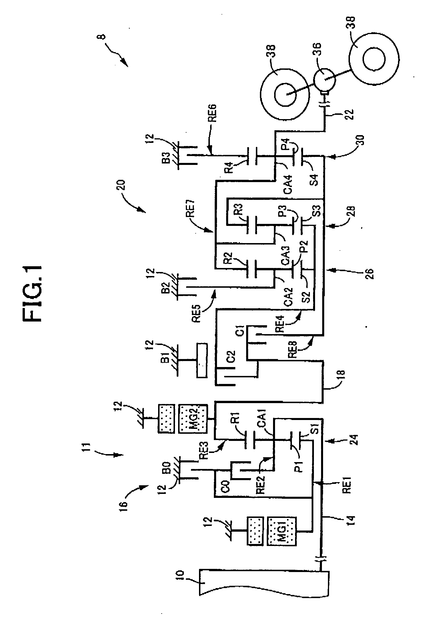
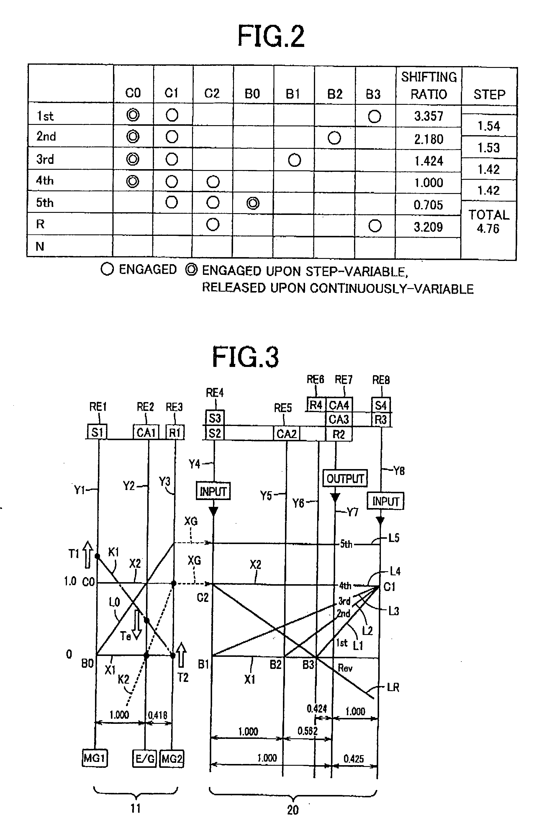
[0062]FIG. 1 is a skeleton view illustrating a vehicular drive apparatus, to which the present invention is preferably applied, which is used for a hybrid vehicle including a drive power source composed of an engine 10 and first and second motor generators MG1 and MG2. As shown in FIG. 1, a shifting mechanism 8 includes following elements in series, which include an input shaft 14 disposed on a common axis within a transmission case 12 (hereinafter referred to as a “case 12”), serving as a non-rotary member, which is mounted on a vehicle body, a switchable type shifting portion 11 directly connected to the input shaft 14 or indirectly connected thereto through a pulsation absorbing damper (vibration damping device) not shown, a step-variable type automatic shifting portion 20 (hereinafter referred to as an “automatic shifting portion 20”) connected to the...


PUM


Abstract

An engine start-up control device for a vehicle is provided with a structure which prevents the occurrence of an uncomfortable shock arising from amplified engine load torque fluctuation caused by resonance, when an output of a first motor generator starting up an engine by driving the same is limited. With a second motor generator having reactive torque restricting the rotation of a transfer member, the first motor generator rotatably drives a sun gear to crank the engine for start-up thereof. When this takes place, if the output of the first motor generator is limited, torque reference reactive-force control is executed to control reactive torque of the second motor generator in accordance with a predetermined torque whereby when the engine load torque exceeds a predetermined value, a rotation speed variation of the transfer member is permitted against reactive torque such that the rotation speed variation of the transfer member allows engine load torque to escape for thereby precluding engine load torque fluctuation to be amplified due to resonance.

Description

TECHNICAL FIELD[0001]The present invention relates to an engine start-up control device for a vehicle, and, more particularly to an engine start-up control when an output of a first electric motor for starting up an engine by driving (cranking) the same is limited.BACKGROUND ART[0002]There has been known an engine start-up control device for a vehicle which includes a differential mechanism connected to an engine generating a drive power by combustion of fuel, a first electric motor, and a reactive-force receiving member whose rotation is restricted with a reactive torque controlled by a reactive-force control device. The engine start-up control device for the vehicle has an engine start-up control device for starting up the engine by driving the same by the first electric motor with the reactive-force control device caused to restrict the rotation of the reactive-force receiving member. One example of such engine start-up control device for the vehicle is disclosed in Patent Docume...

Claims


Application Information

Patent Timeline
Patent Type & Authority Applications(United States)
IPC IPC(8): F02N11/00B60L50/16
CPCB60K1/02B60W20/15B60K6/445B60K6/547B60L2240/421B60L2240/423B60L2240/441B60L2240/445B60L2240/485B60L2240/486B60W10/06B60W10/08B60W10/115B60W10/30B60W20/00B60W2510/0638B60W2510/0676B60W2510/068B60W2510/0685B60W2510/081B60W2510/107B60W2510/244B60W2510/246B60W2520/10B60W2520/105B60W2520/28B60W2530/10B60W2540/10B60W2540/12B60W2540/16B60W2710/0605B60W2710/0616B60W2710/083F02N11/00F02N11/006F02N2300/104Y02T10/6239Y02T10/6286Y02T10/642B60Y2400/435Y10T477/675Y10T477/30B60K6/365Y02T10/62Y02T10/64
Inventor IMAMURA, TATSUYATABATA, ATSUSHIIMAI, KEITAIWASE, YUJIKAKINAMI, TAKUMA
Owner TOYOTA JIDOSHA KK
Learn More