
Temperature control device

a temperature control device and temperature control technology, applied in the direction of lighting and heating apparatus, instruments, domestic cooling devices, etc., can solve the problems of inability to quickly change the temperature control device requires a long period of time in order, and the temperature inside the temperature adjustment unit b> cannot be changed quickly

Inactive Publication Date: 2010-05-13
CKD +1
View PDF8 Cites 17 Cited by
  • Summary
  • Abstract
  • Description
  • Claims
  • Application Information

AI Technical Summary

Benefits of technology

[0008]The present invention solves the aforementioned problem, and an object thereof is to provide a temperature control device that can, when controlling the temperature of a controlled object at a desired level by circulating a fluid in a temperature adjustment unit arranged in the vicinity of the controlled object, quickly achieve the desired temperature of the controlled object.
[0038]Note that the thirteenth aspect of the invention may be provided with heating side temperature detecting means upstream from the adjustment means along the heating pathway, and cooling side temperature detecting means upstream from the adjustment means along the cooling pathway. In this case, the effect of the temperature gradient on the detecting means can be suitably inhibited by prohibiting the discharge of fluid from the heating pathway and the cooling pathway.

Problems solved by technology

The aforementioned temperature control device requires a long period of time in order to change the desired temperature of a controlled object.
Because of this, the temperature inside the temperature adjustment unit 106 cannot be quickly changed, and thus the temperature of the controlled object cannot be quickly changed.

Method used


Image

  • Temperature control device
  • Temperature control device
  • Temperature control device

Examples


first embodiment

[0054]A first embodiment of the temperature control device according to the present invention will be described below with reference to the drawings.

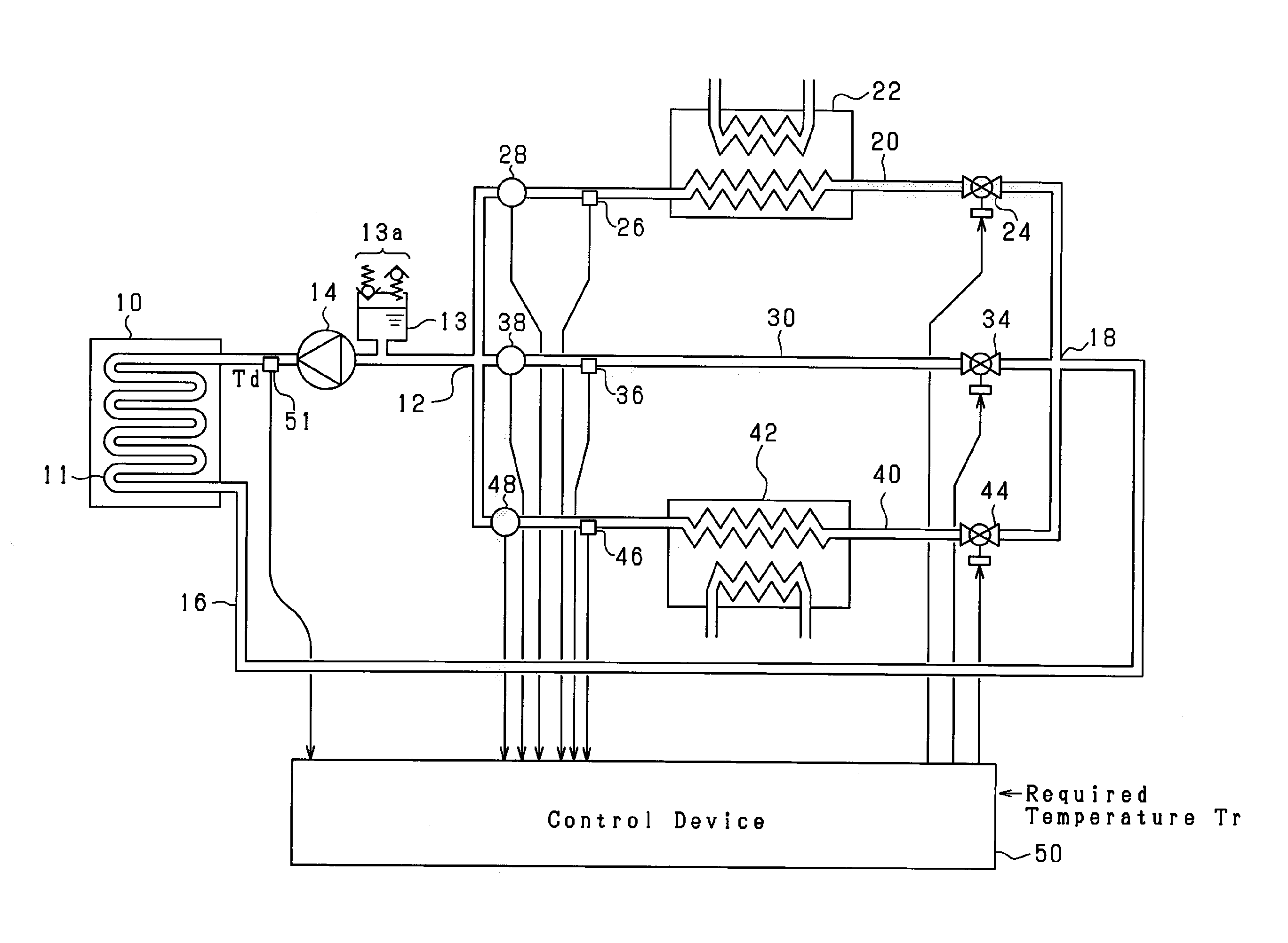
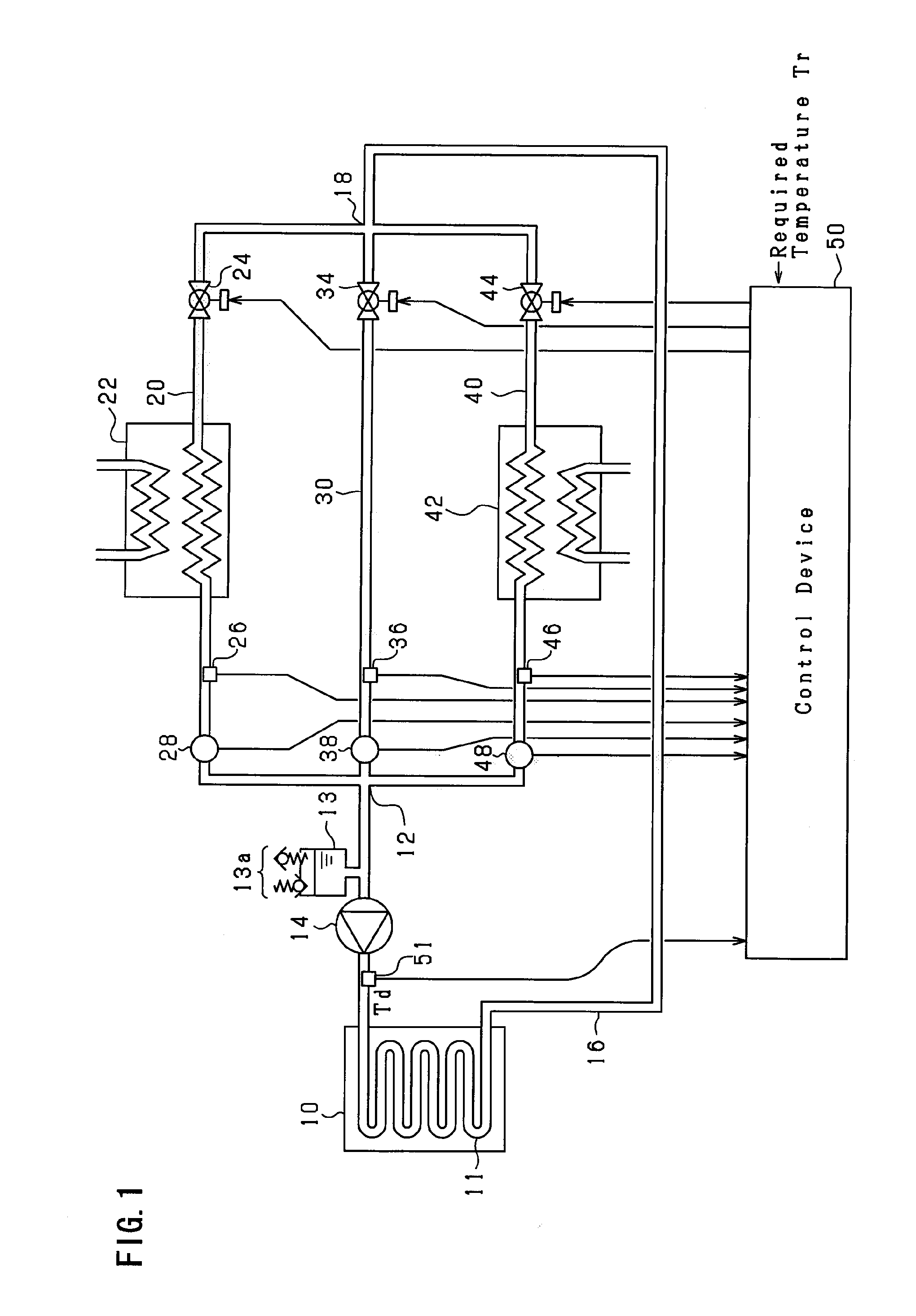
[0055]FIG. 1 shows the overall construction of the temperature control device according to the present embodiment.

[0056]The illustrated temperature control device is employed in, for example, processes / manufacturing steps in the bioengineering field and the chemical engineering field, bioengineering / chemical experimentation, and manufacturing processes for precision machinery such as semiconductor devices, etc. The temperature control device comprises a temperature adjustment plate 10. The temperature adjustment plate 10 exchanges heat energy with a controlled object by supporting a controlled object placed thereon. More specifically, a pathway (temperature adjustment unit 11) is provided in the interior of the temperature adjustment plate 10, and has a non-compressible fluid flowing therein (preferably a liquid medium (liquid temperatu...

second embodiment

[0110]A second embodiment will be described below with reference to the drawings that are focused on the points that differ from the first embodiment.

[0111]FIG. 8 shows the overall construction of the temperature control device according to the present embodiment. As illustrated, in the present embodiment, a discharge pathway 60 that allows fluid to flow circumventing the cooling valve 24 is connected between the upstream and downstream sides of the cooling valve 24 along the cooling pathway 20. In addition, a discharge pathway 62 allows fluid to flow circumventing the heating valve 44 is connected between the upstream and downstream sides of the heating valve 44 along the heating pathway 40.

[0112]These discharge pathways 60 and 62 are sufficiently smaller than the path dimensions of either of the cooling pathway 20 and the heating pathway 40. This is in order to allow the discharge pathways 60 and 62 to discharge a minute amount of fluid from the upstream side of the cooling pathwa...

third embodiment

[0117]A third embodiment will be described below with reference to the drawings that are focused on the points that differ from the first embodiment.

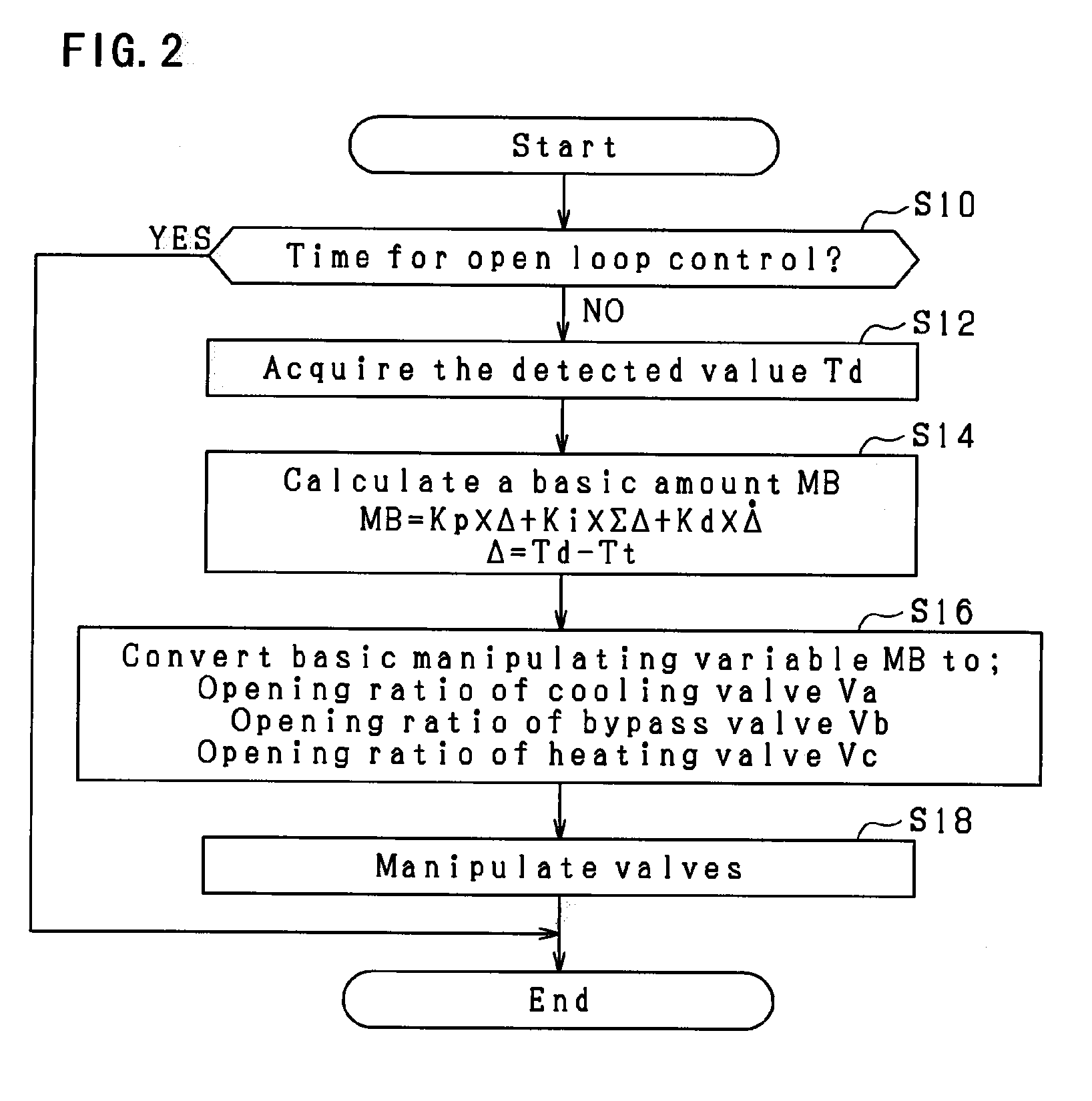
[0118]FIG. 9 shows the relationship between the basic manipulating variable MB according to the present embodiment and the opening ratio Va, Vb and Vc of the cooling valve 24, the bypass valve 34, and the heating valve 44. As illustrated, in the present embodiment, the opening ratio Va of the cooling valve 24 and the opening ratio Vc of the heating valve 44 are set so as not to be in a completely closed state. In other words, the opening ratio Va of the cooling valve 24 will monotonically decrease in accordance with an increase in the basic manipulating variable MB when the basic manipulating variable MB is less than zero, and will be at the smallest opening ratio (>0) when the basic manipulating variable MB is zero or more. In addition, the opening ratio Vc of the heating valve 44 will monotonically increase in accordance with an incre...


PUM


Abstract

The temperature control device comprises a heating pathway that heats and circulates the fluid in the temperature adjustment unit, a cooling pathway that cools and circulates the fluid in the temperature adjustment unit, a bypass pathway that circulates the fluid in the temperature adjustment unit without passing the fluid through the heating pathway and the cooling pathway, an adjustment means that adjusts a flow ratio of the fluid that is supplied from the heating pathway, cooling pathway, and bypass pathway to the temperature adjustment unit, and a flow means that flows the fluid in order to circulate the fluid, and wherein a heating unit for heating the fluid is arranged in the heating pathway, and the flow means is disposed downstream from the heating unit along at least one of the pathways for circulating the fluid.

Description

[0001]The present application claims priority based on Japan Patent Application No. 2008-289465 filed on Nov. 12, 2008, and the entire contents of that application is incorporated by reference in this specification.FIELD OF THE INVENTION[0002]The present invention relates to a temperature control device that controls the temperature of a controlled object at a desired level by circulating a fluid in a temperature adjustment unit arranged in the vicinity of the controlled object.BACKGROUND OF THE INVENTION[0003]FIG. 12 shows this type of temperature control device. As illustrated, fluid inside a storage tank 100 is drawn by a pump 102, and is discharged to a heating unit 104. The heating unit 104 is comprised of a heater or the like, and is capable of heating the fluid to be supplied to a temperature adjustment unit 106. The fluid that has passed through the temperature adjustment unit 106 will be supplied to a cooling unit 108. The cooling unit 108 is capable of cooling the fluid to...

Claims


Application Information

Patent Timeline
Patent Type & Authority Applications(United States)
IPC IPC(8): F25B29/00F28F27/02
CPCF25B29/00F25D17/02F24H9/20G05D23/00
Inventor KOKUBO, NORIOHIROSE, YASUHISAKUSAKA, KAZUHIKONISHIKAWA, KEIICHIMINATANI, TAKAHIRO
Owner CKD
Learn More