
Noise-dampening shield structure for rock drilling apparatus

a shield structure and rock drilling technology, which is applied in the direction of manufacturing tools, transportation and packaging, and well accessories, etc., can solve the problems of noise from drilling, difficulty in implementation, and constant problem of drilling

Active Publication Date: 2010-05-13
SANDVIK MINING & CONSTR OY
View PDF3 Cites 10 Cited by
  • Summary
  • Abstract
  • Description
  • Claims
  • Application Information

AI Technical Summary

Benefits of technology

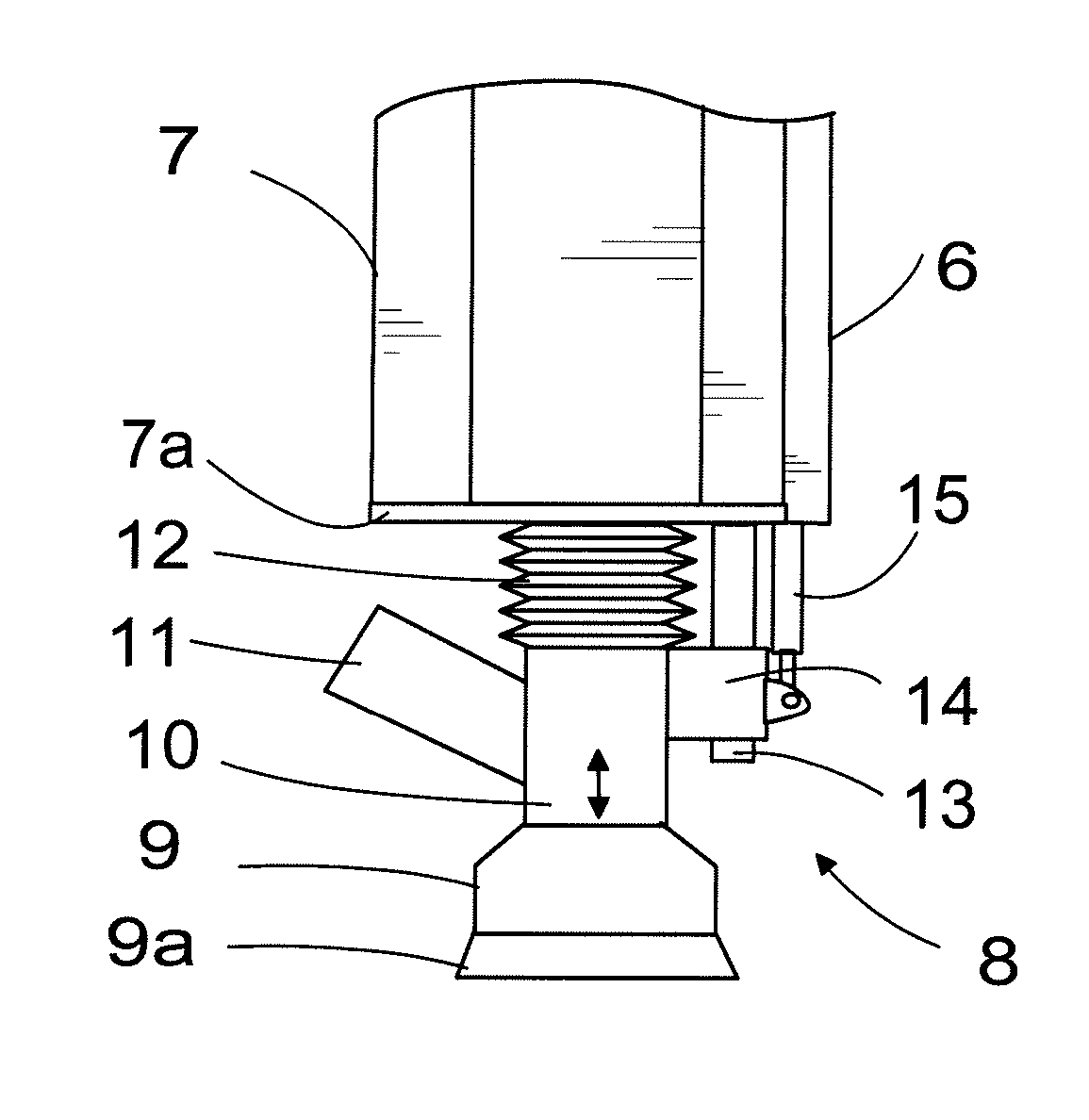
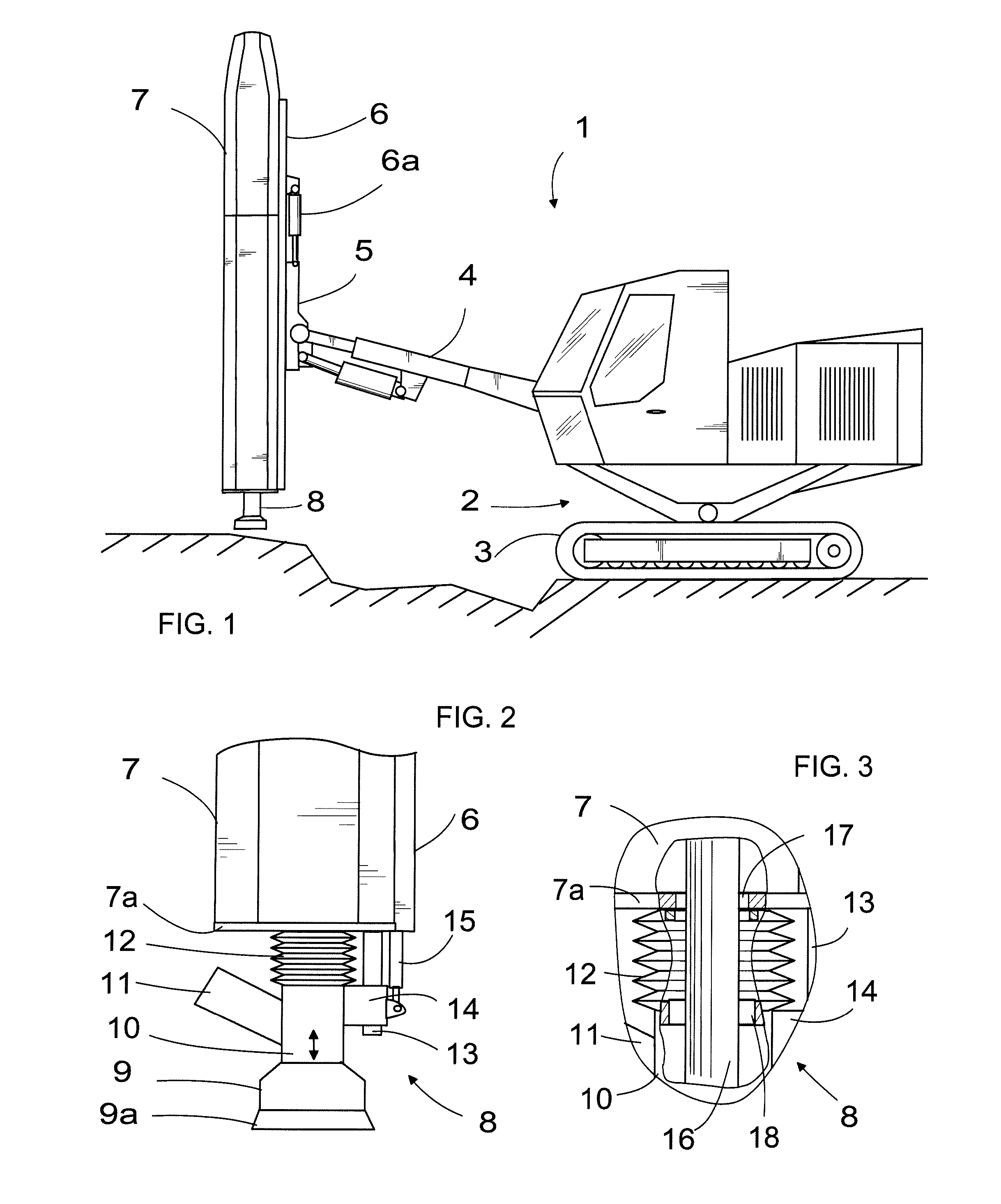
[0006]The essential idea of the invention is that the shield structure comprises as a sound damper a tubular shield flexible at least in its longitudinal direction, which shield tightly closes the space between the shield parts in such a way that noise cannot get directly to the surrounding air. According to an embodiment of the invention, the tubular shield is manufactured of elastic material. According to still another embodiment, the tubular shield is formed of bellows that are attached, by one end, to a sound-dampening housing and, by the other end, to a suction nozzle to be placed upon the drill hole. Hence, the suction nozzle can be moved relative to the sound dampening housing in the axial direction of the drill rod, and the bellows protect the drill rod, dampening noise continuously without gaps. The bellows are also easy to mount and thus also easy to change if they get damaged.

Problems solved by technology

A typical problem in rock drilling is noise.
The noise, which propagates even quite widely to the surroundings, keeps causing more and more problems, particularly in the vicinity of housing areas.
The problem with all these solutions is that they are difficult to implement or they do not dampen the noise over the entire area of the drill.
Particularly the noise dampening at the end of the housing, where the drill bit and the drill rod come out of the housing during the drilling, is not good.
A problem with this solution is that there remains a gap between the parts, and the dampening is not as efficient as it could be.

Method used


Image

  • Noise-dampening shield structure for rock drilling apparatus
  • Noise-dampening shield structure for rock drilling apparatus

Examples


Embodiment Construction

[0011]The same parts are denoted with the same numerals in all figures, and they are not explained separately every time unless it is necessary for the sake of clarity.

[0012]FIG. 1 schematically shows a rock drilling apparatus 1 provided with a base 2. The base is usually provided with wheels or rollers, in this case by way of example with rollers 3. A boom 4 which, in a manner known per se, may consist of one or more boom parts, in the figure by way of example of one part, is attached to the base 2 in a manner known per se. The boom 4 may be any boom structure known per se; therefore, it is not necessary to explain the boom in greater detail. In a manner known per se but not shown in the figure, the boom 4 is articulated to the base 2 so as to enable the boom to be turned to a desired angle with respect to the base by means of power members known per se, such as pressure medium cylinders or the like.

[0013]One of the boom 4 is provided, turnably therewith, with a cradle 5 which, in ...


PUM

PropertyMeasurementUnit
Flexibilityaaaaaaaaaa
Elasticityaaaaaaaaaa

Abstract

The invention relates to a shield structure of a rock drilling apparatus for dampening noise, the rock drilling apparatus comprising a feed beam whose one end is a drilling end, whereby the drilling end of the feed beam comprises a first shield part mounted immovably relative to the feed beam, and a second shield part mounted movably relative to the feed beam. A tubular shield flexible at least in its longitudinal direction is mounted between the shield parts, the shield being tightly attached by its ends to the first and the second shield part.

Description

BACKGROUND OF THE INVENTION[0001]The invention relates to a shield structure of a rock drilling apparatus for dampening noise, the rock drilling apparatus comprising a feed beam whose one end is a drilling end, whereby the drilling end of the feed beam comprises a first shield part mounted immovably relative to the feed beam, and a second shield part mounted movably relative to the feed beam in its longitudinal direction, whereby both shield parts comprise an opening through which a drill rod, which is connected to a rock drill moving during the drilling on the feed beam, travels during the drilling.[0002]When drilling rock, drill apparatuses are used which comprise one or more booms mounted on a base, and a drill movably mounted on a feed beam provided on the boom. Often the feed beam is also installed at an end of a boom movably in its longitudinal direction by a separate cradle so as to enable the feed beam to be arranged in a desired position and in a desired direction for drill...

Claims


Application Information

Patent Timeline
IPC IPC(8): B25D17/11E21B7/02E21B15/00
CPCB25D17/11B25D2222/57B25D2250/231E21B7/025E21B15/04E21B7/02
Inventor PELTOLA, SEPPOHAAVISTO, ARI
Owner SANDVIK MINING & CONSTR OY
Learn More