
Adjustable wall-hanger assembly

Inactive Publication Date: 2010-05-13
ALEO DINO D
View PDF16 Cites 41 Cited by
  • Summary
  • Abstract
  • Description
  • Claims
  • Application Information

AI Technical Summary

Benefits of technology

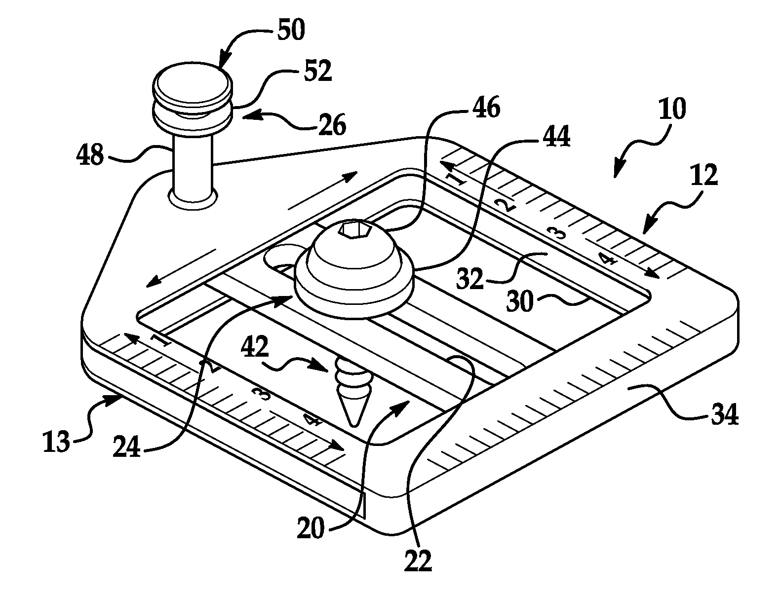
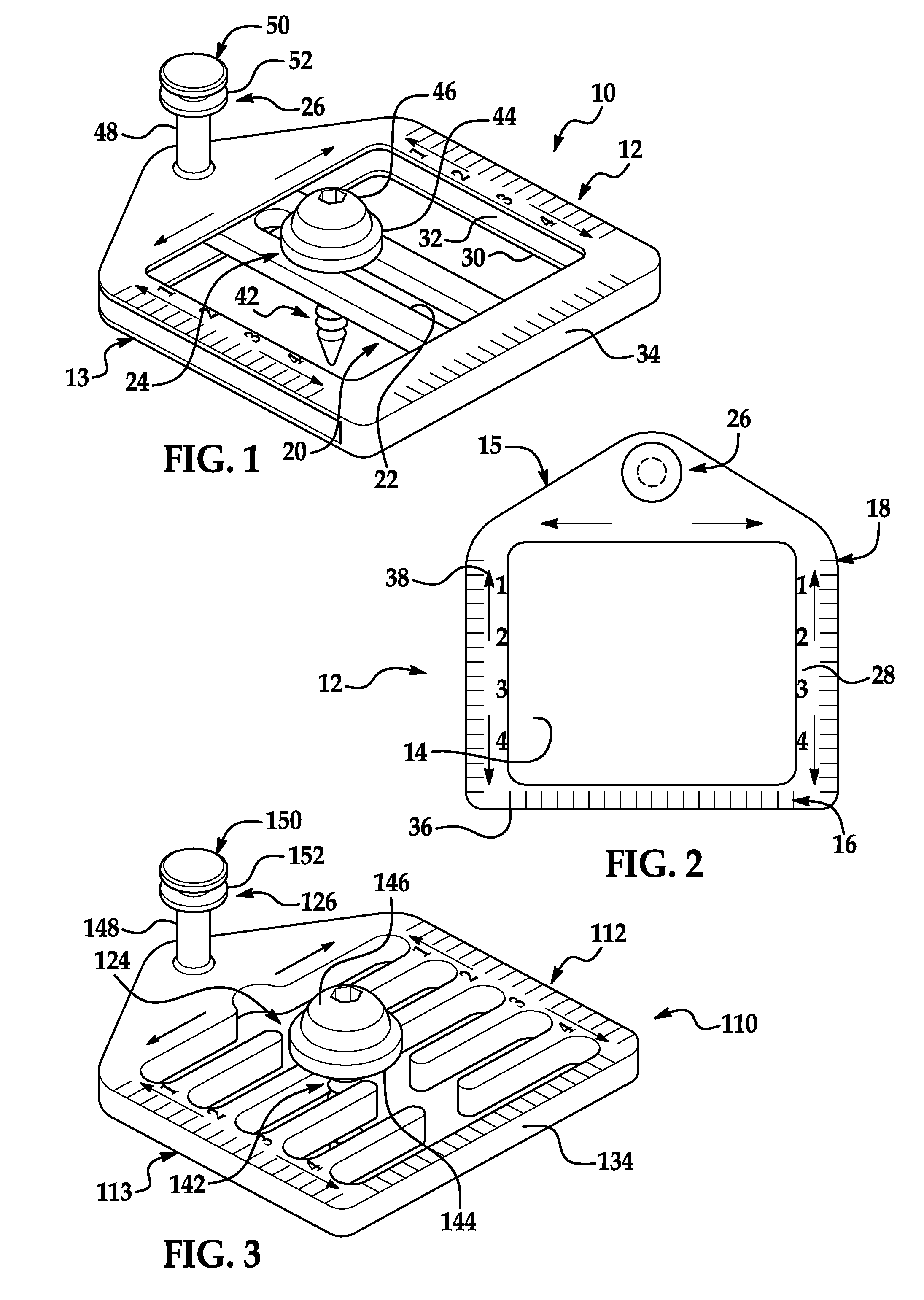
[0010]The invention overcomes the problems in the related art in an adjustable wall-hanger assembly comprising a hanger adapted to be secured to a wall and defining an opening of an interior of the hanger. A hanger slide is mounted to the hanger, is adapted to slide continuously substantially horizontally or vertically in the opening of the hanger, and defines a slot of an interior of the hanger slide extending substantially the other of horizontally or vertically with respect to the hanger slide. A mounting fastener is received through the slot of the hanger slide and adapted to slide continuously along the slot and be fastened to the wall to mount the assembly to the wall. A combination of the continuous substantially horizontal and vertical sliding of the hanger slide and mounting fastener allows for substantially infinite placement of the mounting fastener in the opening of the hanger. A hanger hook is fixedly connected to and extends outwardly from the hanger and substantially overlies the opening of the hanger for supporting an object hung on the hanger hook.
[0011]An advantage of the adjustable wall-hanger assembly of the invention is that it perfectly places / aligns the object—such as a picture, photograph, painting, mirror, collectible, calendar, or corresponding frame—on the wall.

Problems solved by technology

However, these and other of the known adjustable wall hangers do not perfectly place / align the wall décor or corresponding frame on the wall surface.
More specifically, they do not adjust in two ways to accommodate imperfections of the wall décor or corresponding frame and / or construction of the wall surface.
They do not adjust in also a continuous manner.

Method used


Image

  • Adjustable wall-hanger assembly
  • Adjustable wall-hanger assembly
  • Adjustable wall-hanger assembly

Examples


Embodiment Construction

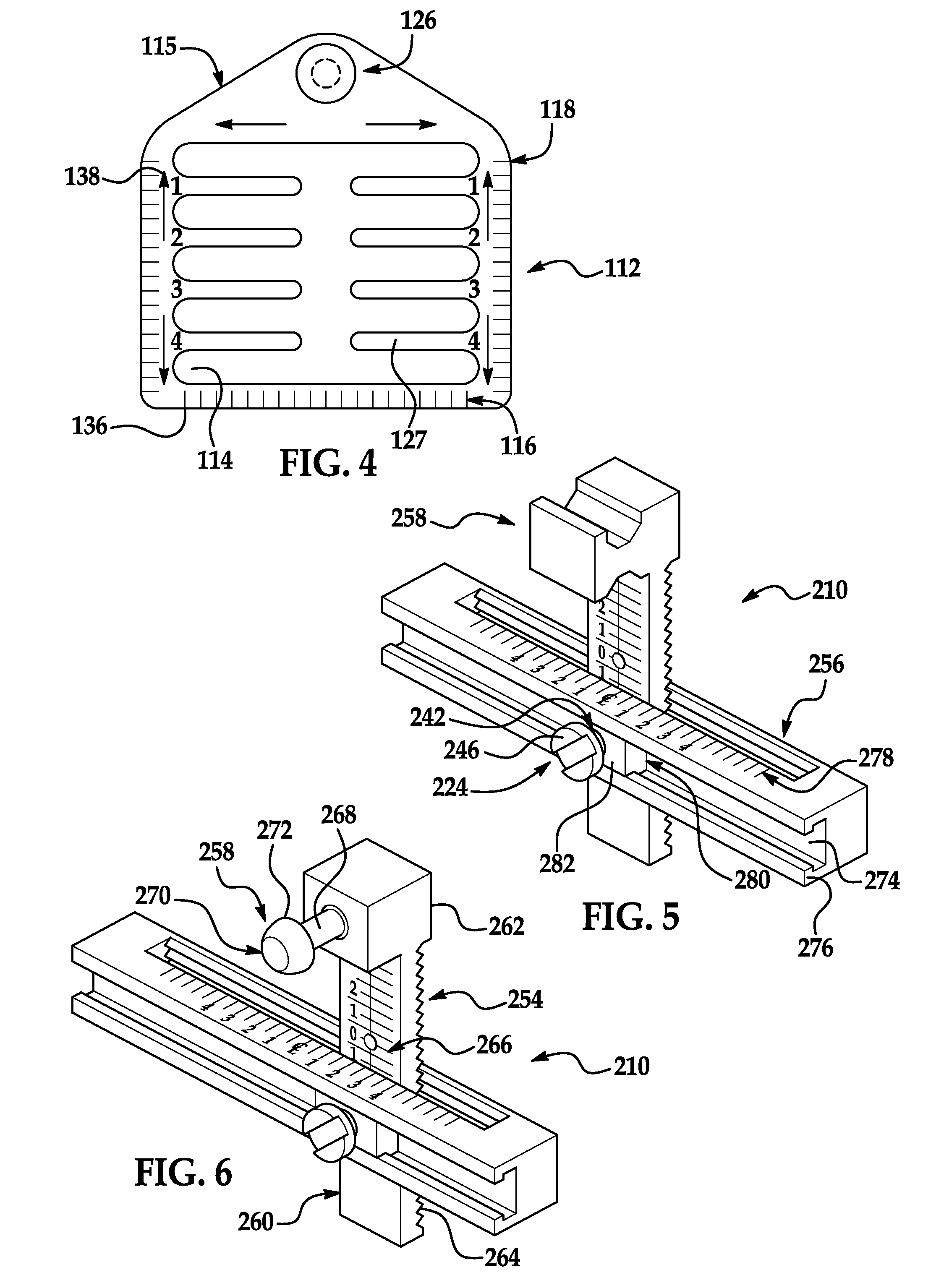
[0026]An assembly for adjustably hanging an object to a wall according to the invention is generally indicated at 10, 110, 210 in FIGS. 1 through 6, where like numerals are used to designate like structure throughout the various embodiments of the assembly 10, 110, 210 disclosed herein. Although the assembly 10, 110, 210 is designed to be attached to a vertical wall for adjustably hanging or suspending wall décor—such as a picture, photograph, painting, mirror, collectible, calendar, or corresponding frame—on a surface of the wall, the assembly 10, 110, 210 is described below for adjustably hanging or suspending specifically a picture frame.

[0027]It should be appreciated by those having ordinary skill in the related art that the wall can have any suitable shape, size, structure, and texture and structural relationship with the assembly 10, 110, 210. It should be so appreciated also that the wall can be made of any suitable material—such as plaster and wood. It should be so appreciat...


PUM


Abstract

An adjustable wall-hanger assembly comprises a hanger adapted to be secured to a wall and defining an opening of an interior of the hanger. A hanger slide is mounted to the hanger, is adapted to slide continuously substantially horizontally or vertically in the opening of the hanger, and defines a slot of an interior of the hanger slide extending substantially the other of horizontally or vertically with respect to the hanger slide. A mounting fastener is received through the slot of the hanger slide and adapted to slide continuously along the slot and be fastened to the wall to mount the assembly to the wall. A combination of the continuous substantially horizontal and vertical sliding of the hanger slide and mounting fastener allows for substantially infinite placement of the mounting fastener in the opening of the hanger. A hanger hook is fixedly connected to and extends outwardly from the hanger and substantially overlies the opening of the hanger for supporting an object hung on the hanger hook.

Description

REFERENCE TO RELATED APPLICATION[0001]This application claims benefit to U.S. Provisional Patent Application 61 / 198,922 filed Nov. 12, 2008 and entitled “Perfect-Placement Adjustable Wall-Hanger Assembly.”BACKGROUND OF INVENTION[0002]1. Field of Invention[0003]The invention relates, generally, to a wall hanger and, more particularly, to such a hanger that is adjustable.[0004]2. Description of Related Art[0005]Various adjustable wall hangers are known. Each such hanger generally is adapted to be attached to a surface of a vertical wall for adjustably hanging or suspending wall décor—such as pictures, photographs, paintings, mirrors, collectibles, calendars, and corresponding frames—on the wall surface.[0006]For example, U.S. Pat. No. 7,201,357 discloses a vertically adjustable wall hanger that comprises a hanger and a hanger mount. The hanger includes a main hanger body, a first set of serrations defined in side-to-side spaced relation to one another on a back side of the main hanger...

Claims


Application Information

Patent Timeline
IPC IPC(8): A47G1/24A47B95/00G01D21/00
CPCA47G1/202A47G1/164
Inventor ALEO, DINO D.
Owner ALEO DINO D
Learn More