Electric power generating apparatus

a technology of electric power generation and electric power, which is applied in the direction of mechanical equipment, mechanical energy handling, machines/engines, etc., can solve the problems of affecting the reciprocation affecting the electrical performance of the permanent magnet, and the magnetic flux of the permanent magnet disposed in the non-magnetic tube-like case leaks outside the case, so as to achieve stable operation of generating electric power

Inactive Publication Date: 2010-05-13
SONY CORP
View PDF4 Cites 15 Cited by
  • Summary
  • Abstract
  • Description
  • Claims
  • Application Information

AI Technical Summary

Benefits of technology

[0010]The present invention has been made in view of the above-mentioned circumstances, and it is desirable to provide an electric power generating apparatus that is advantageous for preventing the leakage of the magnetic flux to the outside while securing electric power generation efficiency and preventing itself from being affected by an external magnetic field.
[0012]According to the embodiment of the present invention, the casing is covered with the shield case, with the result that the magnetic flux of the permanent magnet is prevented from leaking to the outside of the casing.
[0014]Further, even in a case where another magnetic body is disposed near the casing, the reciprocation of the permanent magnet is prevented from being hindered, which is advantageous for ensuring a stable operation of generating electric power.
[0015]In addition, even in a case where a plurality of electric power generating apparatuses are aligned, the reciprocation of the permanent magnet is prevented from being hindered, which is advantageous for ensuring a stable operation of generating electric power.

Problems solved by technology

However, in the electric power generating apparatus in related art as described above, a magnetic flux of the permanent magnet disposed in the nonmagnetic tube-like case leaks outside the case.
When there is, for example, a magnetic card or the like, a watch, or a CRT-based television near the electric power generating apparatus, the leakage may adversely affect those items.
In addition, because the magnetic flux of the permanent magnet leaks outside the case, in a case where there is another magnetic body near the case, the magnetic body and a leakage field from the case affect each other, with the result that the reciprocation of the permanent magnet may be hindered.
In another situation, because the magnetic flux of the permanent magnet leaks outside the case, in a case where a plurality of electric power generating apparatuses are aligned, leakage magnetic fluxes cause a repulsive force or an attractive force to act, with the result that the reciprocation of the permanent magnet may be hindered.

Method used


Image

  • Electric power generating apparatus
  • Electric power generating apparatus
  • Electric power generating apparatus

Examples


first embodiment

[0029]Embodiments of the present invention will be described with reference to the drawings.

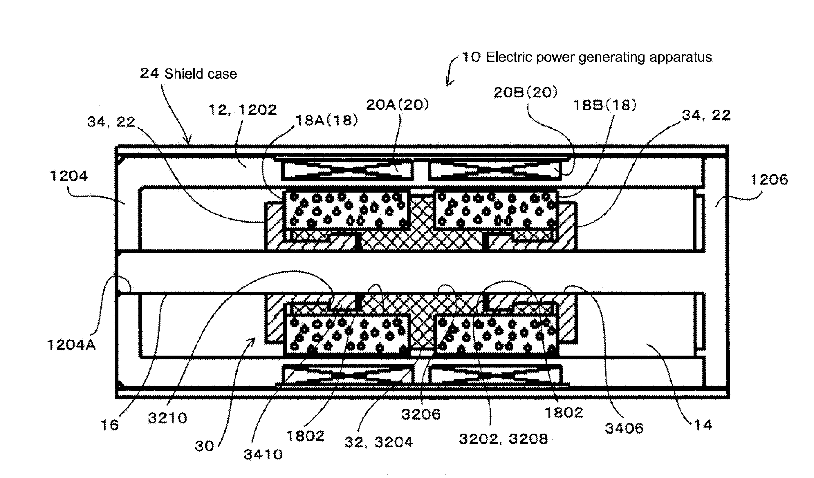
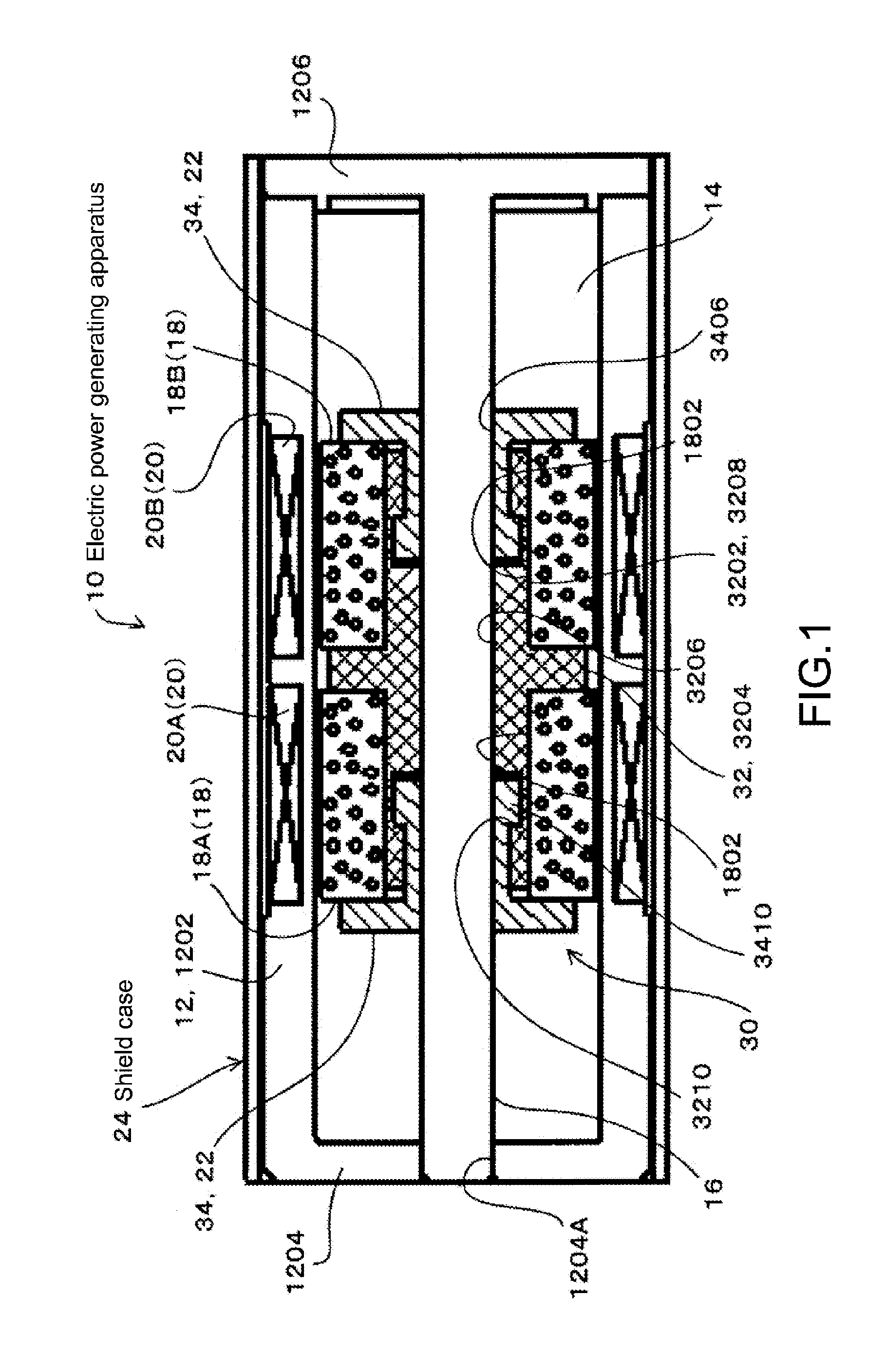
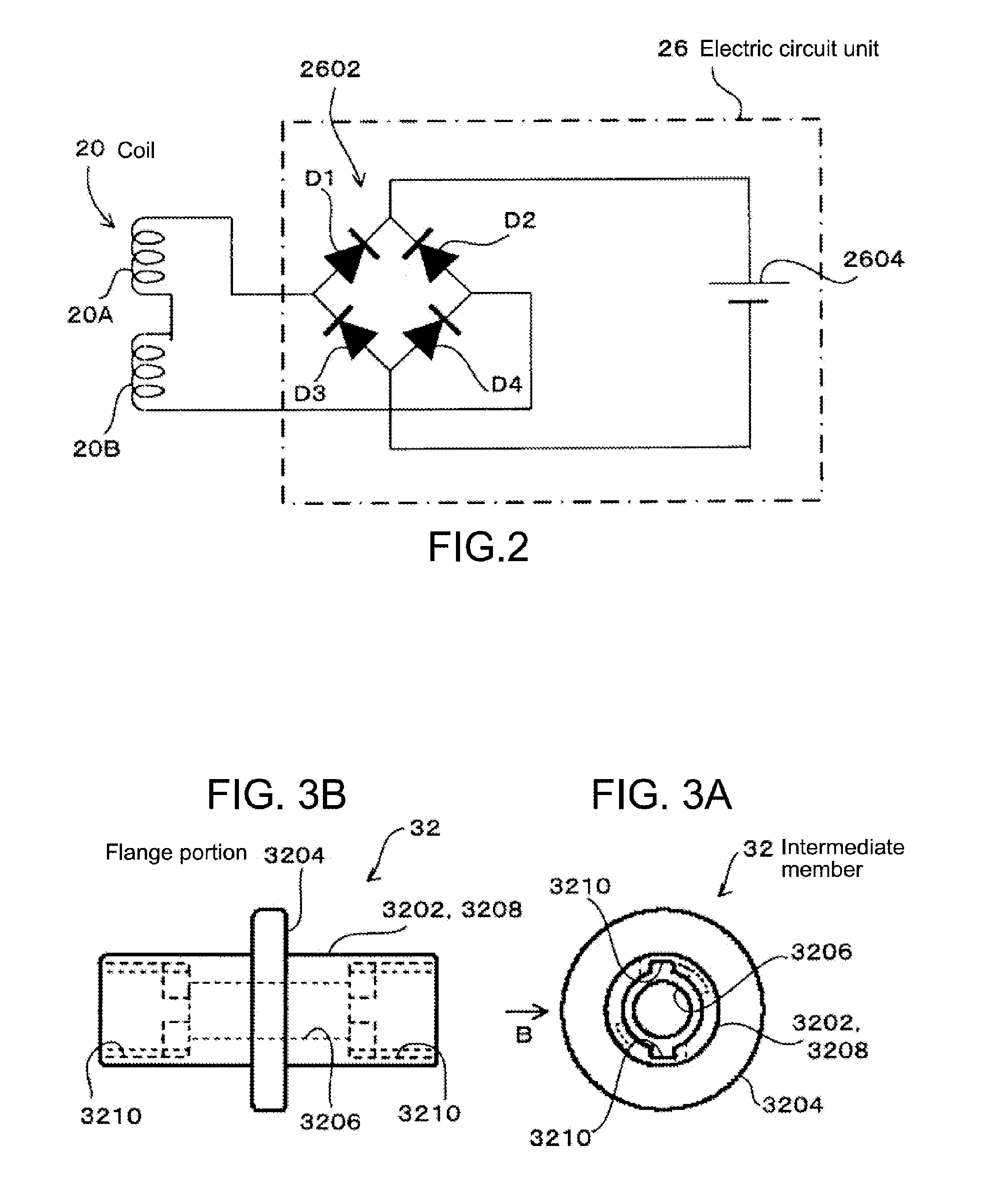
[0030]FIG. 1 is a cross-sectional view showing a structure of an electric power generating apparatus 10 according to this embodiment. FIG. 2 is a circuit diagram of an electric circuit unit 26. FIG. 3A is a front view of an intermediate member 32, and FIG. 3B is a side view of the intermediate member 32 viewed from a side thereof in a direction of the arrow B of FIG. 3A. FIG. 4A is a front view of a cap member 34, and FIG. 4B is a cross-sectional view of the cap member 34 taken along the line B-B of FIG. 4A.

[0031]The electric power generating apparatus 10 includes a casing 12, a space portion (interior space) 14, a guide shaft 16, a permanent magnet 18, a coil 20, a buffer member 22, and a shield case 24 that are shown in FIG. 1, and further includes the electric circuit unit 26 shown in FIG. 2.

[0032]The casing 12 is made of a nonmagnetic, nonconductive material. In this embodiment, the casin...

second embodiment

[0111]Next, a description will be given on a second embodiment.

[0112]The second embodiment is different from the first embodiment in that the shield case 40 covers an entire area of two end surfaces disposed at the both ends in the longitudinal direction, in addition to the entire area of the circumferential surface of the outer surface of the casing 12, that is, the shield case 40 covers the entire surface of the casing 12.

[0113]FIG. 5 is a cross-sectional view of the electric power generating apparatus 10 according to the second embodiment, and FIG. 6 is an operation explanatory diagram of the electric power generating apparatus 10 according to the second embodiment.

[0114]It should be noted that in the second embodiment and subsequent ones, components that are similar to or the same as those of the first embodiment are denoted by the same reference numerals or symbols, and their descriptions will be omitted.

[0115]As shown in FIG. 5, the shield case 40 includes first, second, and t...

third embodiment

[0127]Next, a description will be given on a third embodiment.

[0128]In the third embodiment, the outline of the electric power generating apparatus 10 is set to be the same as the outline of a casing of a commercially available primary battery or secondary battery.

[0129]FIGS. 7 and 8 are cross-sectional views of the electric power generating apparatus 10 according to the third embodiment.

[0130]As shown in FIG. 7, as in the first embodiment, the electric power generating apparatus 10 includes the casing 12, the space portion 14, the guide shaft 16, the permanent magnet 18, the coil 20, the buffer member 22, a shield case 50, and the electric circuit unit 26.

[0131]The electric power generating apparatus 10 has the same shape as the outline of the commercially available primary battery or secondary battery.

[0132]A positive-electrode terminal portion 52 and a negative-electrode terminal portion 54 are provided in the same shape at the same position as a positive-electrode terminal porti...


PUM


Abstract

Disclosed is an electric power generating apparatus. The electric power generating apparatus includes a casing that is made of a nonmagnetic material and has an outer surface and an interior space, a guide shaft that is made of a nonmagnetic material and provided in the interior space while being supported by the casing, a permanent magnet provided to the guide shaft so that the permanent magnet is capable of being reciprocated, a coil provided on an outer circumference of the interior space, a shield case to cover the outer surface of the casing, the shield case being made of a magnetic material, and an electric circuit unit to output an electric energy generated in the coil by reciprocating the permanent magnet.

Description

BACKGROUND OF THE INVENTION[0001]1. Field of the Invention[0002]The present invention relates to an electric power generating apparatus for manually performing an operation of generating electric power.[0003]2. Description of the Related Art[0004]There have been provided portable electric apparatuses such as a portable music player, a mobile phone, a flashlight, and a portable game machine, which include as a power source an electric power generating apparatus that performs electric power generation by a manual operation.[0005]As the electric power generating apparatus described above, there has been proposed an electric power generating apparatus in which a solenoid coil is wound around an outer circumference of a nonmagnetic tube-like case and a permanent magnet is reciprocated in the tube-like case, thereby generating electric power based on the Faraday's law (see, Japanese Patent Application Laid-open Nos. HEI 10-174411, 2002-374661, 2002-281727, 2005-33917, and 2006-296144).[00...

Claims


Application Information

Patent Timeline
Patent Type & Authority Applications(United States)
IPC IPC(8): F03G5/06H02K35/02
CPCH02K7/1876H02K35/02H02K11/0073H02K11/33
Inventor MOCHIDA, TAKASHIOZAWA, TAKESHIKANEKO, SACHIKO
Owner SONY CORP
Why Eureka
Try Eureka