Magnetic circuit and method of applying magnetic field

a magnetic field and magnetic field technology, applied in the field of magnetic field, can solve the problems of affecting the production efficiency of perpendicular two-layer recording media, etc., to achieve the effect of effective magnetic field thermal treatment, large gap, and increasing the number of magnetic samples to be treated

Inactive Publication Date: 2010-05-13
SHIN ETSU CHEM IND CO LTD
View PDF20 Cites 0 Cited by
  • Summary
  • Abstract
  • Description
  • Claims
  • Application Information

AI Technical Summary

Benefits of technology

[0032]According to the present invention, in addition to a side of the magnetic field application part (the pole side of the magnet), the magnets having pole faces on the magnet gap surfaces are used for applying a magnetic field. Thus it is possible to form a strong magnetic field in a gap between the magnetic field application parts (magnets), thereby effectively performing magnetic field thermal treatment on the magnetic sample.
[0033]Therefore, according to the magnetic circuit of the present invention, it is possible to set a large gap and increase the number of magnetic samples treatable in magnetic field thermal treatment at a time, so that a compact magnetic circuit can be designed.

Problems solved by technology

However, in the longitudinal magnetic recording method, an increase in recording density has been regarded as being limited because of the following problems: when each recording region (magnetic domain) is reduced in size to increase a recording density, the north poles and south poles of adjacent magnetic domains repel each other and result in cancellation of magnetization, so that for a high recording density, it is necessary to reduce the thickness of the magnetic recording layer and reduce the crystal grains in size, and finer crystal grains (smaller volumes) cause a phenomenon such as “thermal fluctuations” in which the magnetization direction of the crystal grains is disturbed by thermal energy and data is deleted.
For these reasons, perpendicular two-layer recording media have serious problems about mass production and productivity in consideration of the evenness of the film thickness and composition, the life of the target, the stability of the process, and the low deposition rate above all.
When the soft magnetic film having such domain walls is used as a soft magnetic under layer for the perpendicular two-layer magnetic recording medium, a leakage magnetic field generated from the domain walls causes isolated pulse noise called spike noise or micro-spike noise, so that the signal reproduction property may be seriously deteriorated.
However, in both of the dry and wet processes, it is not easy to simultaneously form a soft magnetic film with excellent film characteristics and provide the film with magnetic anisotropy having high axial symmetry.
Thus a magnetic field generator tends to be large in size and require external installation and the heat treatment furnace tends to have a complicated configuration.
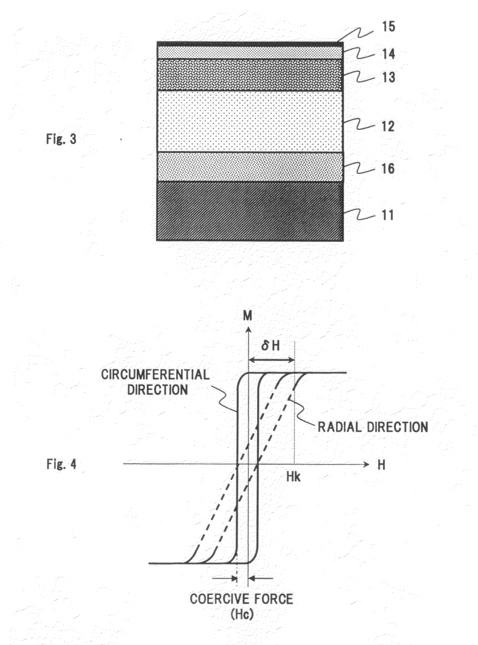
However, it is not easy to provide the soft magnetic under layer of the perpendicular two-layer recording medium with axially symmetric magnetic anisotropy in the in-plane radial direction and the in-plane circumferential direction through magnetic field heat treatment.
This is because in the configuration for applying a magnetic field from the outside of the heat treatment furnace, it is difficult to form a magnetic field in the in-plane radial direction or the in-plane circumferential direction of the substrate disposed in the furnace.
Further, a strong magnetic field is hard to obtain.
Under these constraints, soft magnetic under layers have not been provided with axially symmetric magnetic anisotropy through magnetic field heat treatment.

Method used


Image

  • Magnetic circuit and method of applying magnetic field
  • Magnetic circuit and method of applying magnetic field
  • Magnetic circuit and method of applying magnetic field

Examples


example

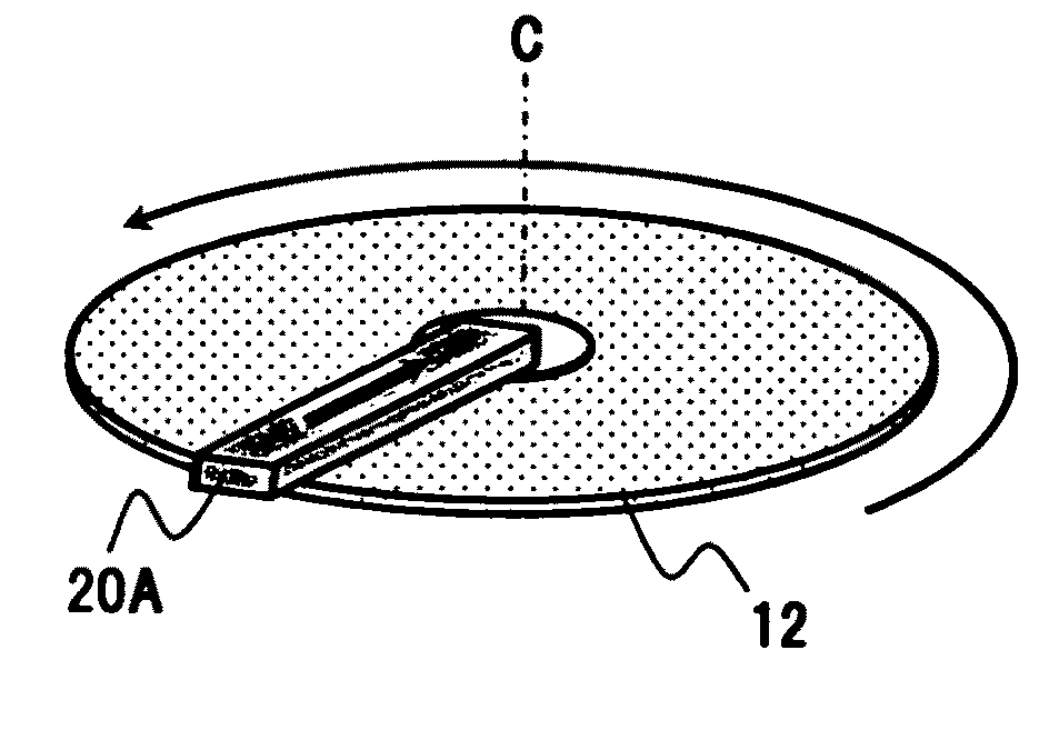
[0094]Magnetic circuits configured as shown in FIGS. 9A and 9B or FIGS. 10A and 10B were produced using a 2-17 type SmCo magnet of Hcj=25 kOe at Br=11 kG and a Nd2Fe14B magnet of Hcj=30 kOe at Br=12.5 kG. The magnetic field application surfaces of these magnetic circuits were each configured by combining a plurality of sets of magnets (the magnets 20 in FIGS. 9A and 9B and the magnets 20B, 20Ba and 20Bb in FIGS. 10A and 10B).

[0095]Further, in order to prevent chips, electric nickel plating (about 10 μm in thickness) was performed on the surfaces of the magnets 20. The magnets 20 were 15 mm to 25 mm in thickness and a gap between the magnet surfaces was 50 mm to 100 mm. Moreover, the magnets were fixed and prevented from coming out of the circuit by tapering the magnets. The five magnetic application surfaces were stacked with four gaps.

[0096]Table 1 shows the measurement results of magnetic field strengths having been measured at the center of the gap by a gauss meter and shows the ...


PUM

PropertyMeasurementUnit
thicknessaaaaaaaaaa
thicknessaaaaaaaaaa
thicknessaaaaaaaaaa

Abstract

In a magnetic circuit for providing magnetic anisotropy in the in-plane radial direction of a soft magnetic under layer, magnets for perpendicular magnetization are respectively provide on the north and south poles of a magnet for horizontal magnetization. When magnetic circuits configured thus are stacked in a plurality of stages, a magnetic field (air-gap magnetic field) formed in a gap between the magnetic circuits is superimposed by magnetic fields from the magnets for perpendicular magnetization as well as a magnetic field from the magnet for horizontal magnetization (in-plane magnetization). The pole faces of the magnets for perpendicular magnetization are disposed closer to the gap between the magnetic circuits, so that a stronger magnetic field can be formed in the gap.

Description

BACKGROUND OF THE INVENTION[0001]1. Field of the Invention[0002]The present invention relates to a magnetic circuit and, more particularly, the present invention relates to a magnetic circuit suitably used for magnetic field heat treatment of a magnetic recording medium substrate and so on and a method of applying a magnetic field by means of the magnetic circuit.[0003]2. Description of the Related Art[0004]In the technical field of information recording, hard disk drives acting as means for magnetically reading and writing information including characters, images, and music have become necessary as primary external recorders or internal recording means of electronic equipment such as personal computers. Such hard disk drives include hard disks serving as magnetic recording media. For hard disks, a so-called “in-plane magnetic recording method (longitudinal magnetic recording method)” is available in which magnetic information is longitudinally written in the plane of a disk and “a ...

Claims


Application Information

Patent Timeline
Patent Type & Authority Applications(United States)
IPC IPC(8): H01F7/02
CPCG11B5/852H01F1/055H01F13/00H01F7/0205H01F7/0247H01F3/14
Inventor OHASHI, KEN
Owner SHIN ETSU CHEM IND CO LTD
Why Eureka
Try Eureka