Speed-reduction alert device

a technology of alert device and speed reduction, which is applied in the direction of signalling/lighting device, vehicle components, optical signalling, etc., to achieve the effect of long reaction tim

Inactive Publication Date: 2010-05-13
WAN JEE
View PDF3 Cites 6 Cited by
  • Summary
  • Abstract
  • Description
  • Claims
  • Application Information

AI Technical Summary

Benefits of technology

[0003]Accordingly, the object of the present invention is to provide a speed-reduction alert device, wherein the deceleration of the first car will alert to the second car so that the driver of the second car will known the action of the first car and thus has a long reaction time.

Problems solved by technology

However this especially occurs when the cars move with high speeds.

Method used


Image

  • Speed-reduction alert device
  • Speed-reduction alert device
  • Speed-reduction alert device

Examples


Embodiment Construction

[0015]In order that those skilled in the art can further understand the present invention, a description will be provided in the following in details. However, these descriptions and the appended drawings are only used to cause those skilled in the art to understand the objects, features, and characteristics of the present invention, but not to be used to confine the scope and spirit of the present invention defined in the appended claims.

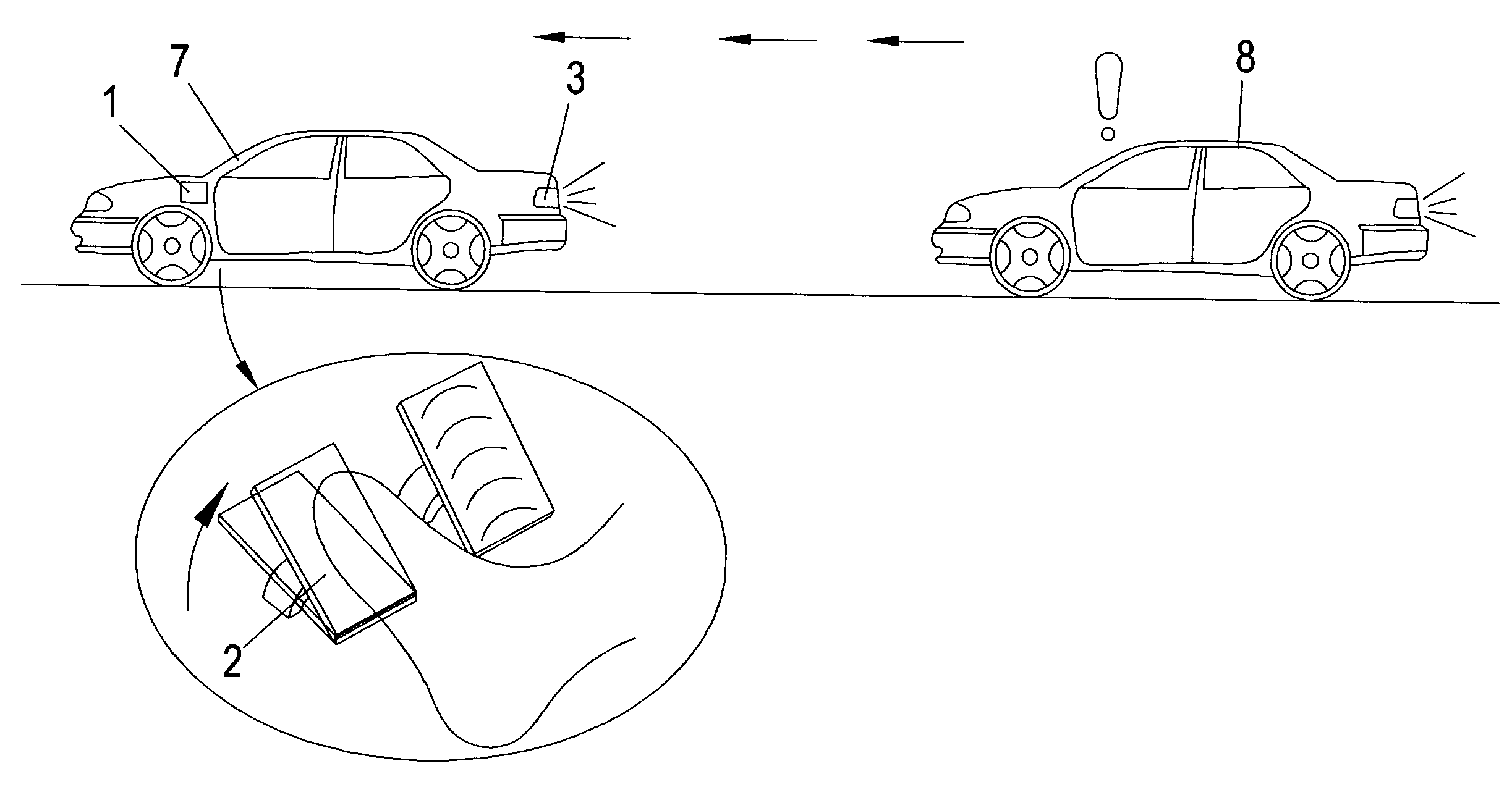
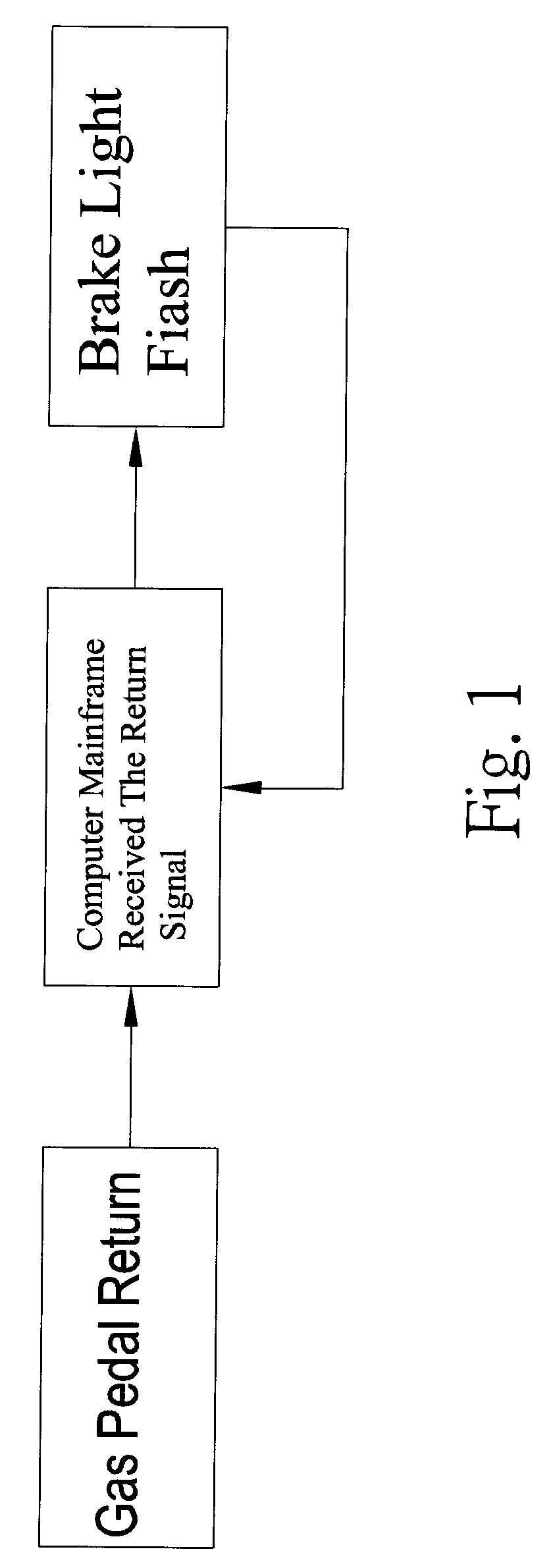
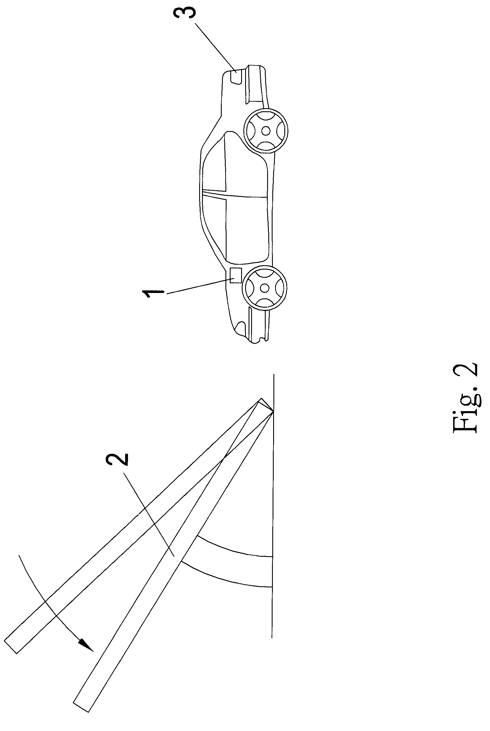
[0016]Referring to FIG. 1, the block diagram of the speed-reduction alert device of the present invention is illustrated. The speed-reduction alert device of the present invention comprises a speed-reduction alert unit 100 installed below a gas pedal 2 for detecting swinging operation of the gas pedal 2 so as to transfer a swing signal outwards;

[0017]A computer main frame 1 is connected to the speed-reduction alert unit 100 for receiving the swinging signals and controlling the flash frequencies, flash periods and change of signals of a brake light...


PUM


Abstract

A speed-reduction alert device comprises a speed-reduction alert unit installed below a gas pedal for detecting swinging operation of the gas pedal so as to transfer a swing signal outwards; a computer main frame connected to the speed-reduction alert unit for receiving the swinging signals and controlling the flash frequencies, flash periods and change of signals of a brake light in a first car to show a deceleration of the first car to a driver of a second car so that the driver of the second car will alert the deceleration of the first car. When the gas pedal is pressed downwards for acceleration, the computer main frame will determine that it is an accelerating signal and the brake light is not actuated; and when the gas pedal is released to move upwards for deceleration, the computer main frame will determine that it is a deceleration signal.

Description

FIELD OF THE INVENTION[0001]The present invention relates to car safety devices, and particularly to a speed-reduction alert device, wherein the deceleration of the first car will alert to the second car so that the driver of the second car will known the action of the first car and thus has a long reaction time. In the present invention, a speed-reduction alert unit is installed to a gas pedal so as to control the flash of the brake light through a computer main frame.BACKGROUND OF THE INVENTION[0002]In the principle of brake lights, when a first car driving along a highway has an accident, the driver of the first car will remove his (or her) leg from the gas pedal and to the brake pedal for braking. Thus the brake light will light up to alert the driver of a second car behind the first car so that the two cars can retain with a safe distance therebetween. However at the moment that the leg of the driver of the first car removes from the gas pedal and moves to the brake pedal, the ...

Claims


Application Information

Patent Timeline
Patent Type & Authority Applications(United States)
IPC IPC(8): B60Q1/50
CPCB60Q1/44B60Q2900/30B60Q1/441
Inventor KAO, HOU-WANG
Owner WAN JEE
Why Eureka
Try Eureka