
GNSS antenna with selectable gain pattern, method of receiving GNSS signals and antenna manufacturing method

a technology of gnss antenna and gain pattern, applied in the field of antennas, can solve problems such as interference with receiver performan

Active Publication Date: 2010-05-13
HEMISPHERE GNSS
View PDF14 Cites 51 Cited by
  • Summary
  • Abstract
  • Description
  • Claims
  • Application Information

AI Technical Summary

Benefits of technology

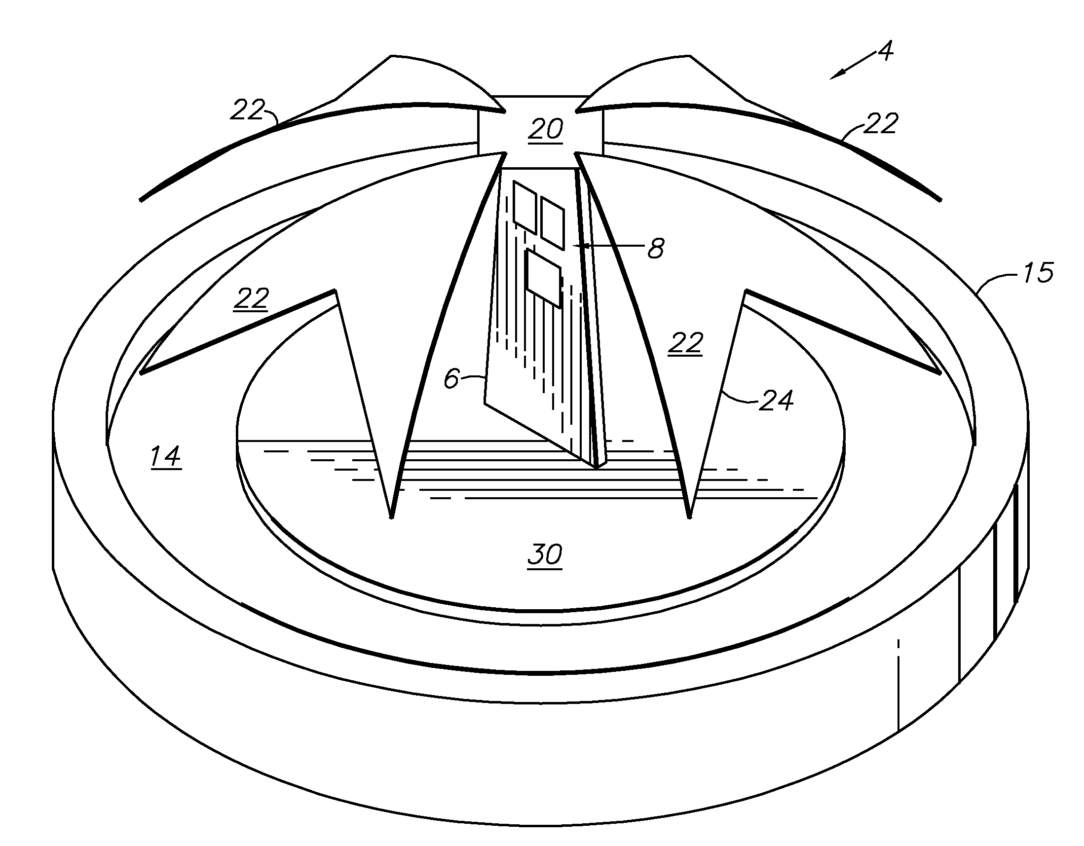
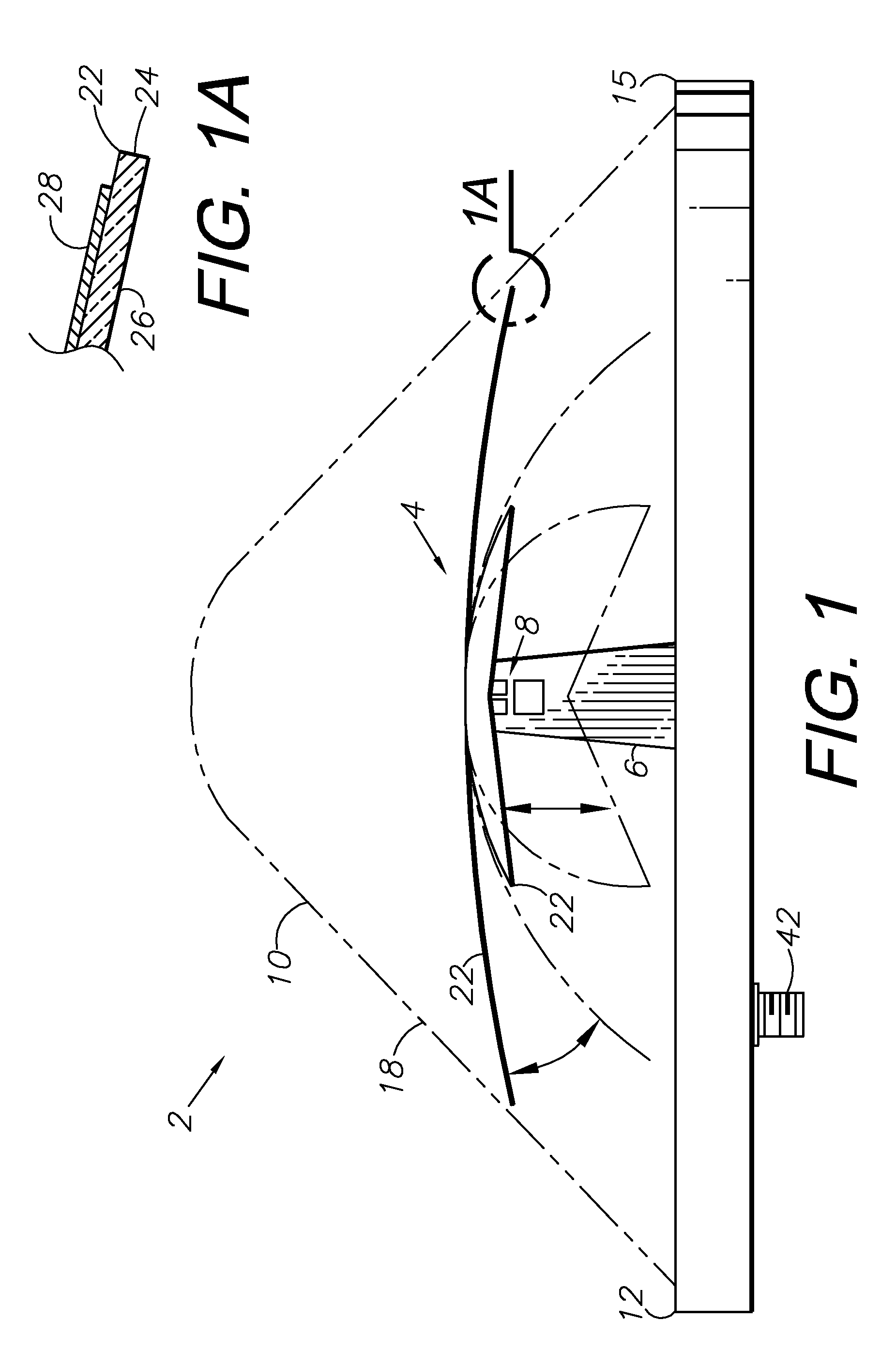
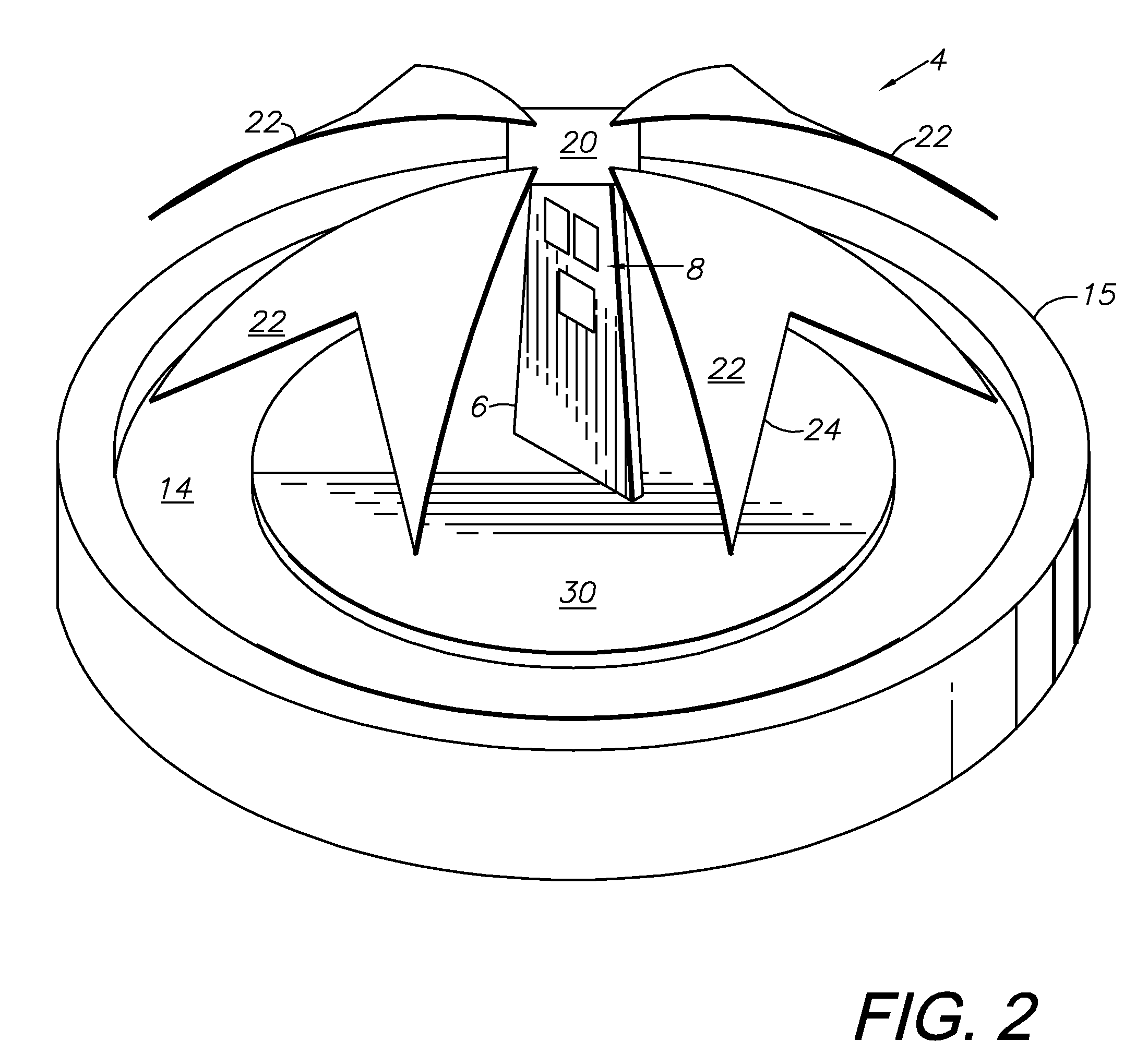
[0011]In the practice of an aspect of the present invention, a crossed-dipole, GNSS antenna with selectable gain patterns is provided. The antenna includes a radiating arm element assembly mounted on an upright PCB support, which is mounted on a ground base. The ground base is mounted on a base PCB with a low noise amplifier (LNA). Antenna gain patterns are selectable for particular applications and operating conditions by varying the radiating arm element configurations, varying the PCB support height and reconfiguring the effective ground base.

Problems solved by technology

Antennas with strong gain patterns at or near the horizon are particularly susceptible to multipath signals, which can significantly interfere with receiver performance based on direct line-of-sight (LOS) reception of satellite ranging signals and differential correction signals (e.g., DGPS).

Method used


Image

  • GNSS antenna with selectable gain pattern, method of receiving GNSS signals and antenna manufacturing method
  • GNSS antenna with selectable gain pattern, method of receiving GNSS signals and antenna manufacturing method
  • GNSS antenna with selectable gain pattern, method of receiving GNSS signals and antenna manufacturing method

Examples


Embodiment Construction

[0029]I. Introduction and Environment

[0030]As required, detailed embodiments of the present invention are disclosed herein; however, it is to be understood that the disclosed embodiments are merely exemplary of the invention, which may be embodied in various forms. Therefore, specific structural and functional details disclosed herein are not to be interpreted as limiting, but merely as a basis for the claims and as a representative basis for teaching one skilled in the art to variously employ the present invention in virtually any appropriately detailed structure.

[0031]Certain terminology will be used in the following description for convenience in reference only and will not be limiting. For example, up, down, front, back, right and left refer to the invention as oriented in the view being referred to. The words “inwardly” and “outwardly” refer to directions toward and away from, respectively, the geometric center of the embodiment being described and designated parts thereof. Sai...


PUM


Abstract

An antenna is provided for GNSS and other applications and includes an adjustable-height vertical support PCB mounted on a ground plane and mounting a crossed-dipole radiating arm element assembly. The gain pattern of the antenna can be varied by constructing the vertical support PCB with different heights or adjusting the height and gain pattern in the field. Vehicles with significant pitch and roll can be provided with low-horizon tracking capability by providing a high-profile antenna configuration. Alternatively, low-profile configurations provide steeper gain pattern rolloff at the horizon for maximal multipath rejection and high accuracy. The droop angles of the radiating arm elements are also adjustable for varying the gain pattern and beamwidth. A matching and phasing network is connected to the radiating arm elements and provides a relatively constant input impedance for the various antenna configurations. Alternative aspects of the invention have different configurations of the radiating arm elements and ground planes.

Description

BACKGROUND OF THE INVENTION[0001]1. Field of the Invention[0002]The present invention relates generally to antennas, and in particular to a broadband, crossed-dipole antenna with selectable gain patterns, which is particularly well-suited for GNSS applications.[0003]2. Description of the Related Art[0004]Various antenna designs and configurations have been produced for transmitting and receiving electromagnetic (wireless) signals. Antenna design criteria include the signal characteristics and the applications of the associated equipment, i.e. transmitters and receivers. For example, stationary, fixed applications involve different antenna design configurations than mobile equipment.[0005]Global navigation satellite systems (GNSS) have progressed within the last few decades to their present state-of-the-art, which accommodates a wide range of positioning, navigating and informational functions and activities. GNSS applications are found in many industries and fields of activity. For ...

Claims


Application Information

Patent Timeline
IPC IPC(8): H01Q1/50H01Q9/16H01Q3/00
CPCH01Q1/42H01Q21/26H01Q9/28
Inventor FELLER, WALTERWEN, XIAOPING
Owner HEMISPHERE GNSS
Learn More