
Switcher control device, switcher control method, and image synthesizing apparatus

Inactive Publication Date: 2010-05-13
SONY CORP
View PDF8 Cites 14 Cited by
  • Summary
  • Abstract
  • Description
  • Claims
  • Application Information

AI Technical Summary

Benefits of technology

[0011]Thus, it is desirable to economically implement superimposition according to the shooting state of a camera without causing degradation of the overall functions in relation to a system using an effects switcher. In addition, it is also desirable to automate adjusting of the position at which an image is superimposed, to downsize the staff necessary to operate a broadcasting system to curtail costs, and to reduce the possibilities of occurrence of operating error caused by manual operations of superimposed positions. In addition, it is also desirable to economically implement suited superimposition in operations of a plurality of cameras.
[0018]As described above, in the embodiment of the invention, when the effects switcher selects an image taken by a camera as a background image, the control unit automatically determines whether a superimposition image is to be superimposed, and instructs the effects switcher to do superimposition based on the determined result. In this case, in order to superimpose the superimposition image on the image taken by the camera, a portion of the circuit in the effects switcher is not exclusively used, the portion of the circuit is used as necessary. In addition, in this case, a superimposition device for cameras is not provided separately from the effects switcher. Therefore, superimposition according to the shooting state of the camera can be economically implemented without causing degradation of the overall functions.
[0019]In addition, in the embodiment of the invention, when the effects switcher selects an image taken by a predetermined camera among a plurality of the cameras, it is determined whether a superimposition image is superimposed on the image taken by the camera based on information about the shooting state of the predetermined camera (such as the position, the angle, and the zoom value). Then, the effects switcher is instructed to superimpose a superimposition image that is to be placed on the image taken by the predetermined camera based on the determined result. Therefore, even though a plurality of the cameras is operating, suited superimposition can be economically implemented.
[0020]In the embodiment of the invention, for example, the control unit may further calculate a position at which a superimposition image is to be superimposed based on angle information and zoom value information about the camera, and based on the calculated result, the control unit may instruct the effects switcher of the position at which the superimposition image is to be superimposed. In this case, because adjusting the superimposed position of the image is automated, the staff necessary to operate a broadcasting system can be downsized to curtail costs, and the possibilities of occurrence of operating error caused by manual operations of superimposed positions can be reduced.

Problems solved by technology

In this case, even though any images taken by the camera are not used, it is difficult to allocate that portion of the circuit for other purposes, which causes degradation of the overall functions.
In this case, although the use of the image taken by the camera is involved in only a small portion of operations, this takes a lot of money.

Method used


Image

  • Switcher control device, switcher control method, and image synthesizing apparatus
  • Switcher control device, switcher control method, and image synthesizing apparatus
  • Switcher control device, switcher control method, and image synthesizing apparatus

Examples


embodiment

1. Embodiment

1-1. Exemplary Configuration of a Broadcast Programming Delivery Control System

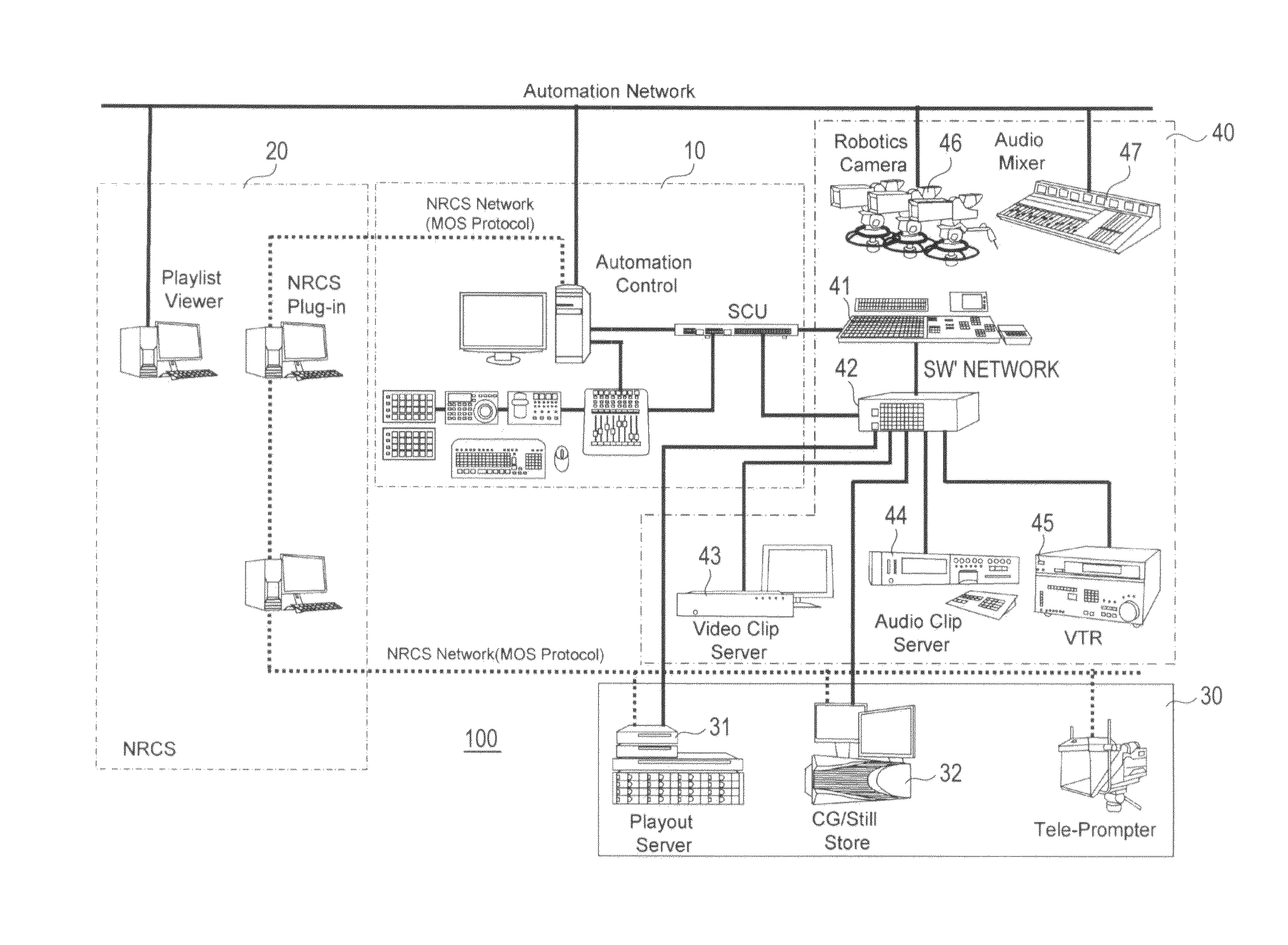
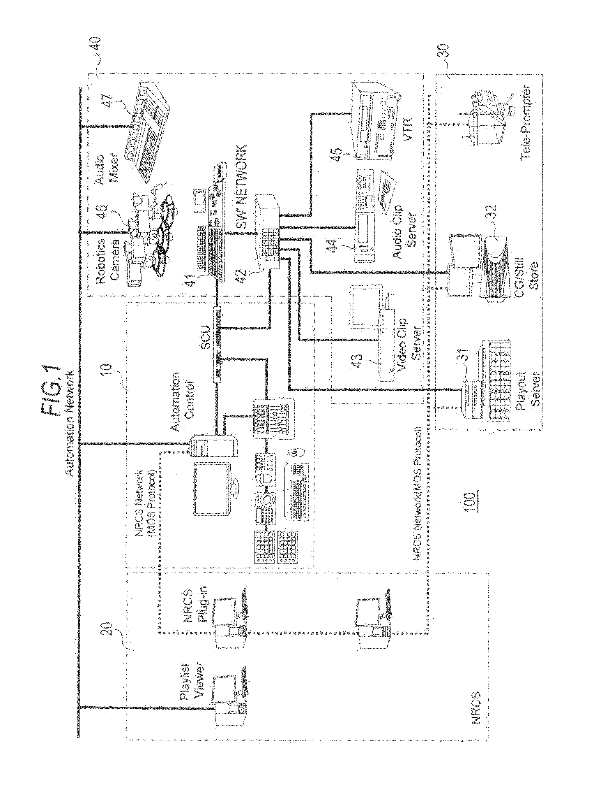
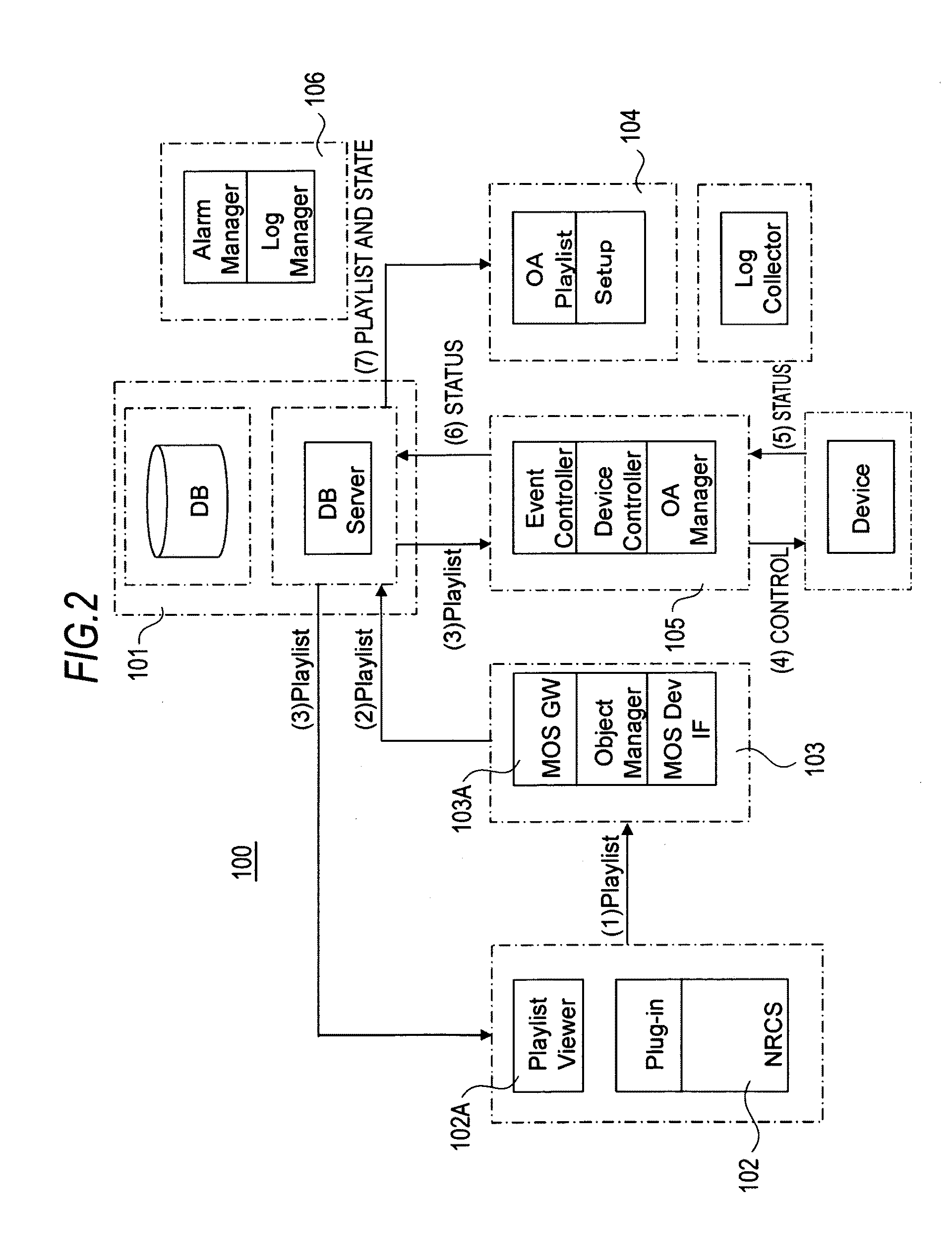
[0051]FIG. 1 shows an exemplary configuration of a broadcast programming delivery control system 100 as an embodiment. This broadcast programming delivery control system 100 has an automation control block 10, a news room control system (NRCS) block 20, an MOS device block 30, and an automation control device block 40.

[0052]The control block 10 controls broadcast programming delivery based on a playlist (cue sheet) formed of a plurality of configurations. Here, the playlist configures a broadcast programming delivery program, and individual cues (individual formations) of the playlist correspond to individual items of the broadcast programming delivery program. The NRCS block 20 conducts management and administration related to news programs such as arrangements for gathering information, placing orders of materials, and making formations of broadcast programming. In the MOS (Media Object Ser...


PUM


Abstract

A switcher control device includes: a superimposition determining unit that determines whether a superimposition image is superimposed on an image taken by a camera based on angle information and zoom value information about the camera in selecting a camera image when an effects switcher selects the image taken by the camera as a background image; and a switcher instructing unit that instructs the effects switcher to superimpose the superimposition image based on a determined result of the superimposition determining unit.

Description

CROSS-REFERENCE TO RELATED APPLICATION[0001]The present application claims priority from Japanese Patent Application No. JP 2008-288719 filed in the Japanese Patent Office on Nov. 11, 2008, the entire content of which is incorporated herein by reference.BACKGROUND OF THE INVENTION[0002]1. Field of the Invention[0003]The present invention relates to a switcher control device, a switcher control method, and an image synthesizing apparatus. More specifically, the invention relates to a switcher control device in which when an effects switcher selects an image taken by a camera as a background image, the switcher control device determines whether a superimposition image is superimposed on the image taken by the camera based on angle information and zoom value information about the camera, and instructs the effects switcher to do superimposition, thereby economically implementing superimposition according to shooting states without causing degradation of the overall functions.[0004]2. De...

Claims


Application Information

Patent Timeline
IPC IPC(8): H04N5/262
CPCH04N5/23203H04N5/76H04N5/262H04N5/23206H04N23/66H04N23/661H04N23/695
Inventor FUJITA, SHINICHINAKAMURA, SENSABURO
Owner SONY CORP
Learn More