Method of fabricating a commutator for a motor

Inactive Publication Date: 2005-02-03
SAMSUNG GWANGJU ELECTRONICS CO LTD
View PDF4 Cites 2 Cited by
  • Summary
  • Abstract
  • Description
  • Claims
  • Application Information

AI Technical Summary

Benefits of technology

[0019] The drawing processing step may use a bar made of a copper containing a silver (Ag) in the range from about 0.01% to about 2.0%. Consequently, the possibility of occurrence of sparking or ring fire can be reduced.
[0020] The method of fabricating the commutator as described above improves the durability and abrasion resistance of the commutator through the liquefied nitrogen heat-proce

Problems solved by technology

With the Mica clamping method, strips of Mica are inserted and clamped between each commutator segment and bushing one by one, which makes the fabrication process of the commutator quite complicated and inconvenient.
Accordingly, this method is rarely used except in cases of large-sized motors.
When the commutator fabricated by the above-described method is employed in a motor, there segment abrasion caused by friction occurs between a carbon brush and the commutator, and the segment abrasion causes the carbon brush to be rapidly abraded.
Moreover, the heat caused by the abrasion of the carbon brush causes particles of the commutator segment to become disconnected, which may create problems to the smooth functioning of the motor.
Also, after a long period of use, a motor tends

Method used


Image

  • Method of fabricating a commutator for a motor
  • Method of fabricating a commutator for a motor
  • Method of fabricating a commutator for a motor

Examples


Embodiment Construction

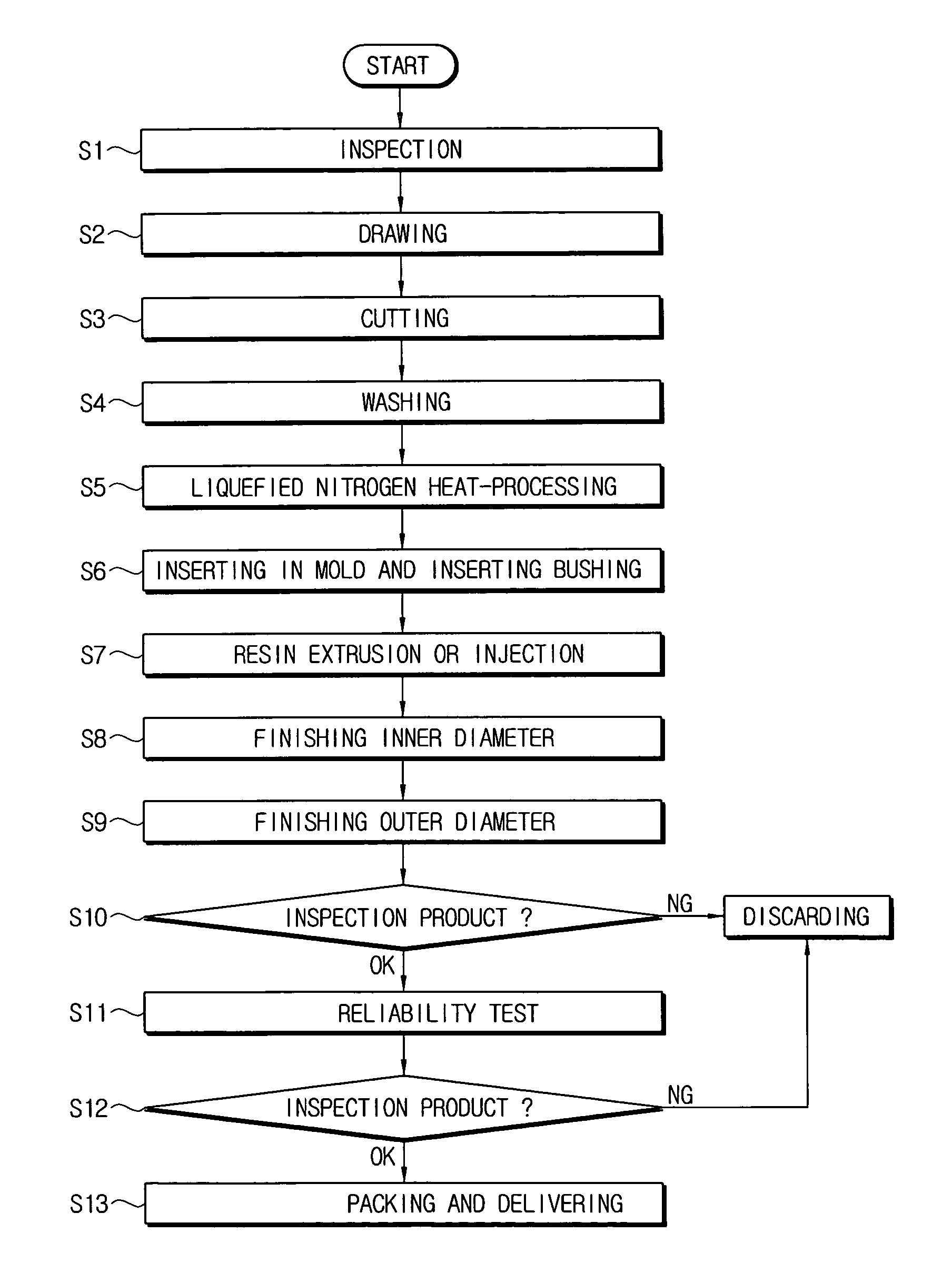
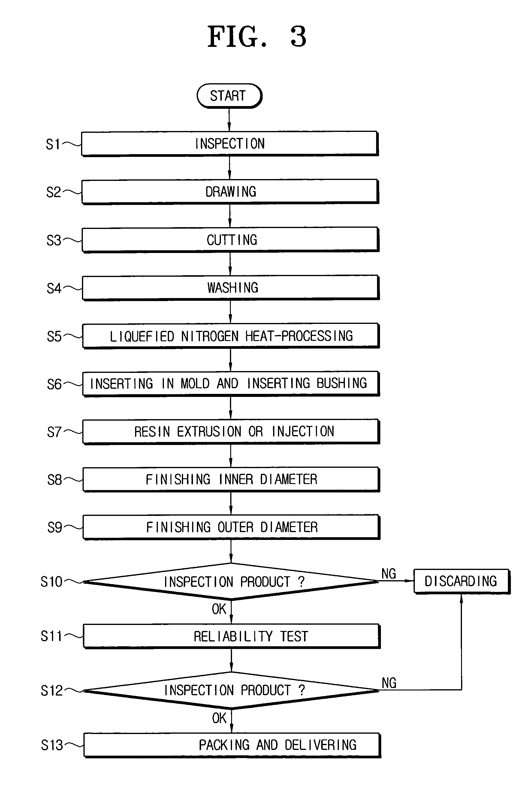
[0029]FIG. 3 is a block diagram of a flowchart showing a step-by-step method of fabricating a commutator for a motor according to an embodiment of the present invention. As shown in FIG. 3, an inspection step (S1) is performed with respect to a circle-shaped copper bar. The bar may use a pure copper wire, and perhaps more preferably, it may use an alloy also comprising silver (Ag) addition ranging from 0.01% at least to 2% by weight at most.

[0030] Next, a drawing step (S2) is performed with respect to the circle-shaped bar to form a segment having a desired thickness.

[0031] The segment formed by the drawing step (S3) is cut to a predetermined size to form a commutator segment.

[0032] The commutator segment is then washed (S4) by using a mixed solution consisting of an abluent, water, and lactic acid.

[0033] After being washed, the commutator segment is deposited into liquefied nitrogen for a predetermined time ranging from 15 minutes to 25 minutes (S5). In one example, the tempera...


PUM

PropertyMeasurementUnit
Percent by massaaaaaaaaaa
Fractionaaaaaaaaaa
Weightaaaaaaaaaa

Abstract

A method of fabricating a commutator for a motor comprises the steps of: drawing a bar into the shape of a plate; forming plural commutator segments having a predetermined size by cutting the plate at appropriate intervals; heat-processing the commutator segments with liquefied nitrogen; inserting the heat-processed commutator segments, and setting the commutator segments in a mold in a circular pattern having a predetermined gap from one another for receiving insulating resin, and inserting a bushing in a central position of the circular pattern of commutator segments; forming an insulating resin layer in the gaps between the commutator segments by extruding or injecting an insulating resin into the mold; and finishing an inner diameter and an outer diameter of the fabricated commutator.

Description

BACKGROUND OF THE INVENTION [0001] 1. Field of the Invention [0002] The present invention relates generally a method of fabricating a commutator for a motor, and more particularly, to a method of fabricating a commutator for a motor, which is capable of preventing a commutator from being extremely abraded due to a friction brush and also having an improved abrasion resistance. [0003] 2. Description of the Background Art [0004] Generally, a commutator for a motor includes plural commutator segments arranged in a motor having a ring pattern, an insulating resin for insulating each commutator segment from other adjacent segments, and a bushing. The commutator segments are usually made of 100% cupper (Cu), and the bushing is centrally disposed in respect of the insulating resin so as to allow a shaft of a rotator to be inserted thereinto. [0005] A segment type motor commutator fabrication method is widely used for fabricating commutators for motors. According to the segment type motor c...

Claims


Application Information

Patent Timeline
IPC IPC(8): H02K13/00H01R43/06H02K15/02
CPCY10T29/49011H01R43/06H02K13/00
Inventor LEE, CHEON-MU
Owner SAMSUNG GWANGJU ELECTRONICS CO LTD
Why Eureka
Try Eureka