

Reading method for mlc memory and reading circuit using the same
- Summary
- Abstract
- Description
- Claims
- Application Information
AI Technical Summary
Benefits of technology
Problems solved by technology
Method used
Image

Examples
first embodiment
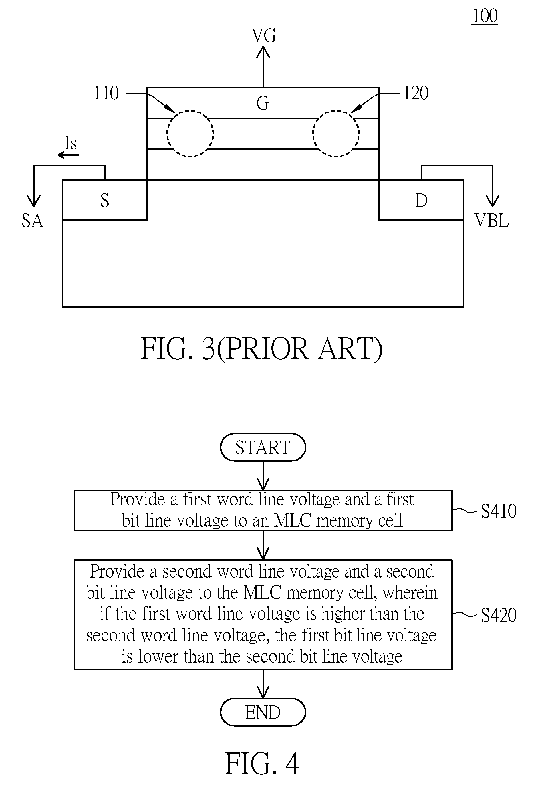
[0023]FIG. 4 is a flow chart showing a reading method for an MLC memory according to a first embodiment of the invention. The method includes the following steps. In step S410, a first word line voltage and a first bit line voltage are provided to an MLC memory cell. In step S420, a second word line voltage and a second bit line voltage are provided to the MLC memory cell, wherein if the first word line voltage is higher than the second word line voltage, the first bit line voltage is lower than the second bit line voltage.
[0024]FIG. 5 is a schematic illustration showing a reading circuit 500 using the reading method for the MLC memory according to the first embodiment of the invention. Referring to FIG. 5, the reading circuit 500 includes a word line voltage controller 510, a bit line voltage controller 520 and a sense amplifier 530. In FIG. 5, the function and the operation method of each element are described by taking an MLC memory cell M of an MLC memory 502 as an example.
[0025...
second embodiment
[0037]FIG. 7 is a flow chart showing a reading method for an MLC memory according to a second embodiment of the invention. Referring to FIG. 7, the method includes the following steps. In step S710, a number of word line voltages are sequentially provided. In step S720, a number of bit line voltages corresponding to the word line voltages are sequentially provided, wherein if one of the word line voltages is higher than another one of the word line voltages, one of the bit line voltages corresponding to the one of the word line voltages is lower than another one of the bit line voltages corresponding to the another one of the word line voltages. In an exemplary embodiment, each of the word line voltages and its corresponding bit line voltage are provided simultaneously. In step S730, current values flowing through the MLC memory cell are detected. In step S740, the data value stored in the MLC memory cell is determined according to the current values. Each current value is the value...
PUM
 Abstract
Description
Claims
Application Information