Supercharge Your Innovation With Domain-Expert AI Agents!

Image reader, image reading system and image reading method

a reading system and image technology, applied in the direction of digital output to print units, instruments, computing, etc., can solve the problems of difficult for users to find the location where the converted image data is stored, adverse effects on the usability of the image reading system, etc., and achieve the effect of processing image data smoothly in the computer

Inactive Publication Date: 2010-05-13
OKI DATA CORP
View PDF7 Cites 30 Cited by
  • Summary
  • Abstract
  • Description
  • Claims
  • Application Information

AI Technical Summary

Benefits of technology

[0007]An object of the application is to disclose an image reader, an image reading system and an image reading method capable of processing image data smoothly in the computer.

Problems solved by technology

However, it is frequently difficult for the user to find the location where the converted image data is stored.
This causes adverse effects on the usability of the image reading system.

Method used


Image

  • Image reader, image reading system and image reading method
  • Image reader, image reading system and image reading method
  • Image reader, image reading system and image reading method

Examples


first embodiment

Modification of First Embodiment

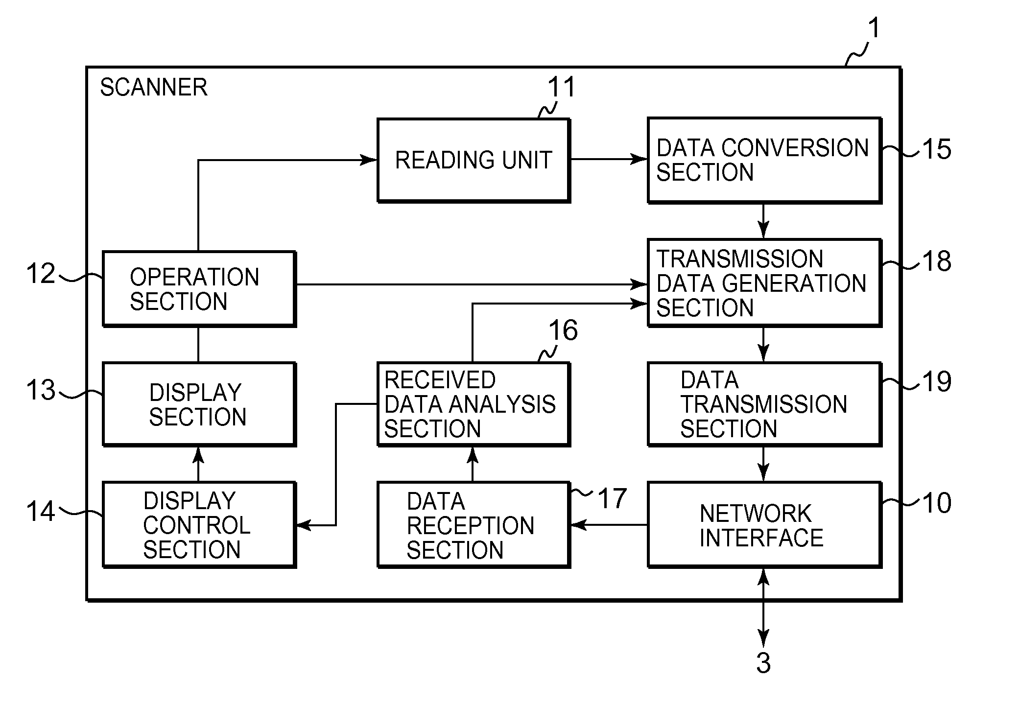
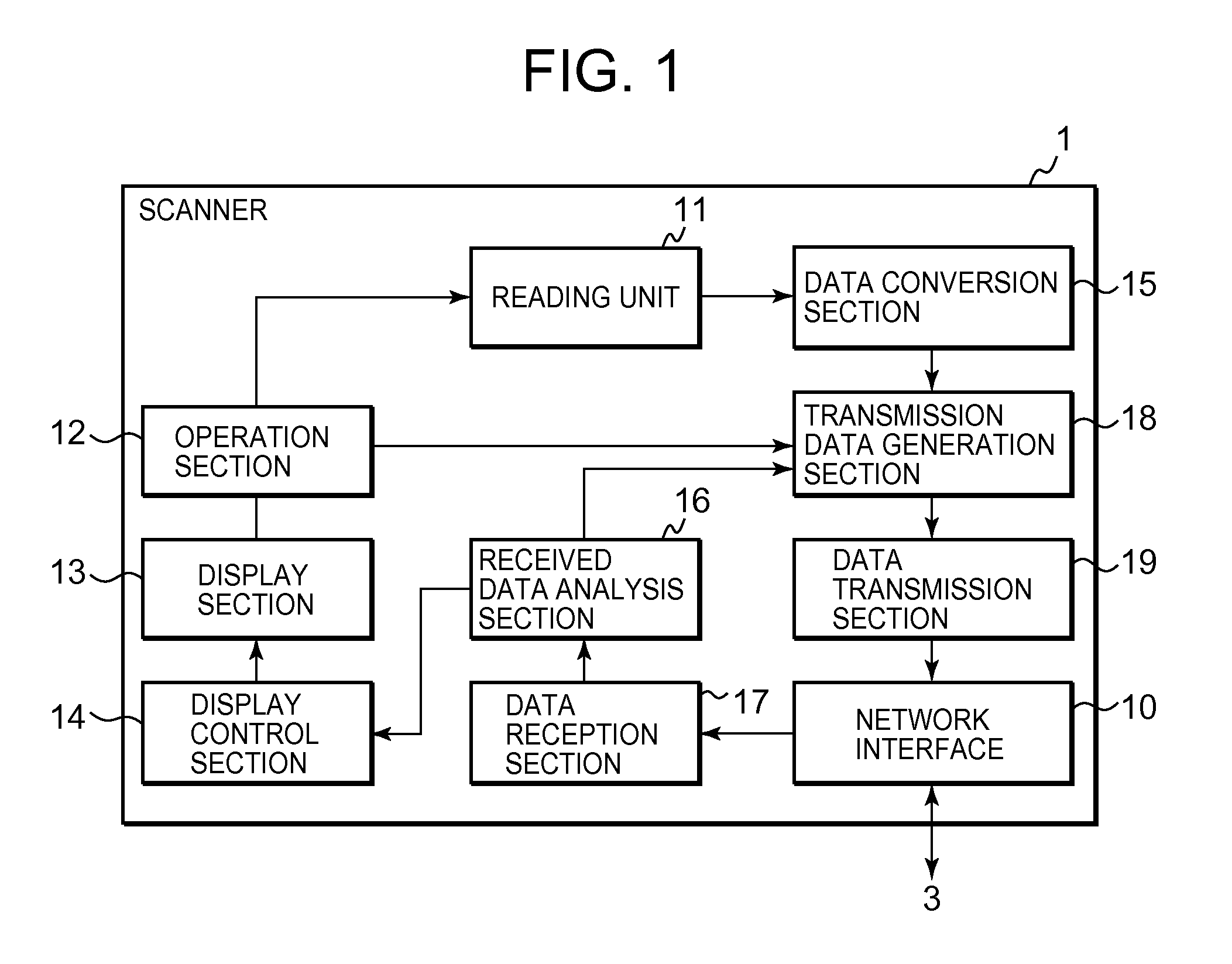
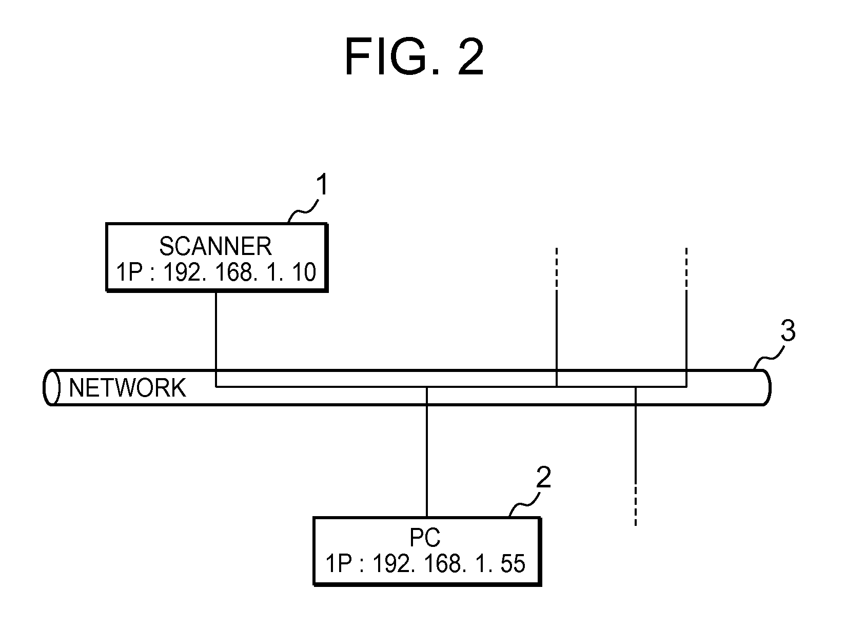
[0073]In the first embodiment, as shown FIG. 12, the storage destination folder for the converted image data has been created in the PC 2 in advance and the path information on the folder is sent to the scanner 1 as part of the terminal information response data. The scanner 1 transmits the converted image data to the PC 2 together with the path information, and then the PC 2 stores the converted image data in the storage destination folder designated by the path information.

[0074]In the modification of the first embodiment, a different folder is provided for each application program. The converted image data from the scanner 1 is stored in a corresponding folder provided for the application program that can process the data. Therefore, path information on the corresponding folder is added to the converted image data when the data is transmitted from the scanner 1 to the PC 2. If the corresponding folder is not in the PC 2, the scanner 1 commands the ...

second embodiment

[0080]FIG. 17 is a block diagram of a scanner 501 according to a second embodiment. FIG. 18 is a configuration diagram of a transmission data generation section 518. The second embodiment differs from the first embodiment in that a designation section 502 is added to the display section 13 and the transmission data generation section 518 is used in place of the transmission data generation section 18. Elements similar to those in the first embodiment have been given the same numerals and their description is omitted.

[0081]Through the designation section 502, the user can select and specify display format items relating to the converted image data that is to be processed by the application program in the PC 2. As shown in FIG. 18, the transmission data generation section 518 includes a generation section 581 that generates image data together with an instruction for starting the application program to process the image data on the basis of data received from the data conversion secti...


PUM


Abstract

An image reader and an external terminal are connected to each other through a network. The image reader includes a reading unit, a reception section, a data conversion section, a transmission data generation section and a transmission section. The reading unit reads an image. The reception section receives terminal information from the external terminal. The data conversion section converts image data read by the reading unit into a predetermined data format based on the terminal information. The transmission data generation section adds additional information, which relates to processing of the converted image data, to the converted image data to generate transmission data. The transmission section transmits the transmission data to the external terminal.

Description

CROSS-REFERENCE TO RELATED APPLICATION[0001]This application claims priority based on 35 USC 119 from prior Japanese Patent Application No. P 2008-289979, filed on Nov. 12, 2008, the entire contents of which are incorporated herein by reference.BACKGROUND OF THE INVENTION[0002]1. Field of the Invention[0003]This application relates to an image reader, an image reading system and an image reading method.[0004]2. Description of the Related Art[0005]A scanner as an image reader capable of sending image data to a computer is well known. When a user specifies a data format of the image data to be read, the scanner converts the image data into the data format and sends the converted image data to the computer. The computer stores the converted image data in a memory. Thereafter, the user starts an application program capable of processing the converted image data to display or edit the data. Japanese Patent Laid-Open No. 2003-177997 discloses one such image reading system.[0006]In the afo...

Claims


Application Information

Patent Timeline
IPC IPC(8): G06F3/12
CPCH04N1/00222H04N1/00225H04N1/33307H04N2201/0015H04N2201/0068H04N2201/0081H04N1/00482H04N2201/3278H04N2201/33321H04N2201/33328H04N2201/33378H04N1/00408H04N2201/3242
Inventor ASANO, YOKO
Owner OKI DATA CORP
Features
  • R&D
  • Intellectual Property
  • Life Sciences
  • Materials
  • Tech Scout
  • Unparalleled Data Quality
  • Higher Quality Content
  • 60% Fewer Hallucinations
Learn More