Method and apparatus for encoding and decoding image

a technology of moving or still images and methods, applied in the field of methods and apparatus for encoding and decoding moving or still images, can solve the problems of encoding efficiency reduction, increasing prediction residual error, etc., and achieves the effect of improving prediction efficiency, and reducing prediction residual error

Inactive Publication Date: 2010-05-13
KK TOSHIBA
View PDF20 Cites 119 Cited by
  • Summary
  • Abstract
  • Description
  • Claims
  • Application Information

AI Technical Summary

Benefits of technology

[0015]According to the present invention, a prediction residual error can be reduced even in a complex texture region in which a texture in a block has a complex directivity. A unidirectional prediction mode having a single prediction direction and a multidirectional prediction mode having different prediction directions can be selected, and a weighted average of prediction signals based on the prediction modes is calculated according to a weighting factor set depending on a prediction direction of a prediction mode and a spatial distance between a prediction pixel and the reference pixel in the multidirectional prediction mode. For this reason, a prediction residual error can be reduced. Therefore, prediction efficiency is improved. As a result, high encoding efficiency can be realized.

Problems solved by technology

In a complex texture region, a prediction residual error increases.
As a result, encoding efficiency reduces.
However, this assumption is not always satisfied, and a prediction residual error may increase.

Method used


Image

  • Method and apparatus for encoding and decoding image
  • Method and apparatus for encoding and decoding image
  • Method and apparatus for encoding and decoding image

Examples


first embodiment

f Syntax Structure

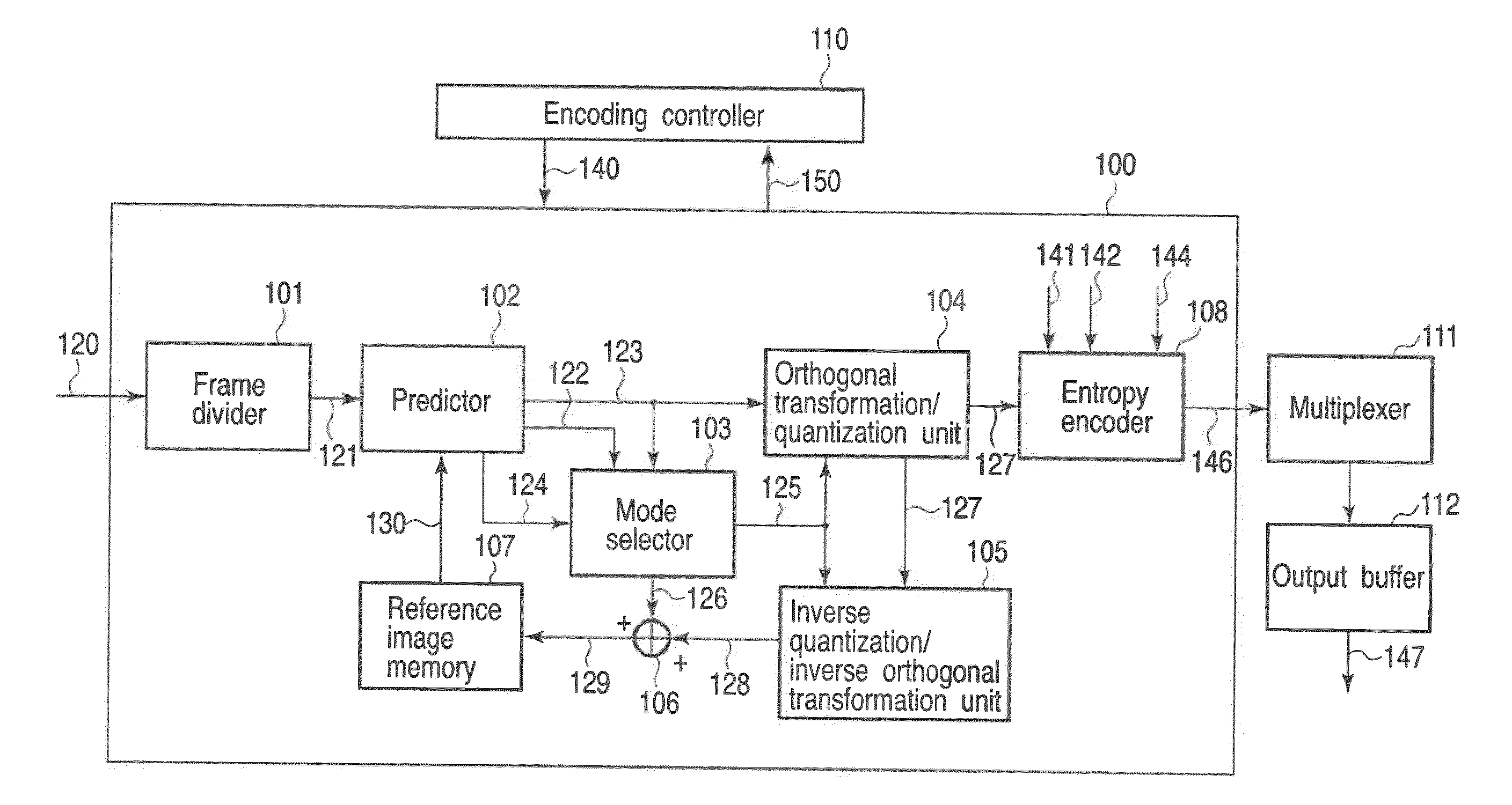
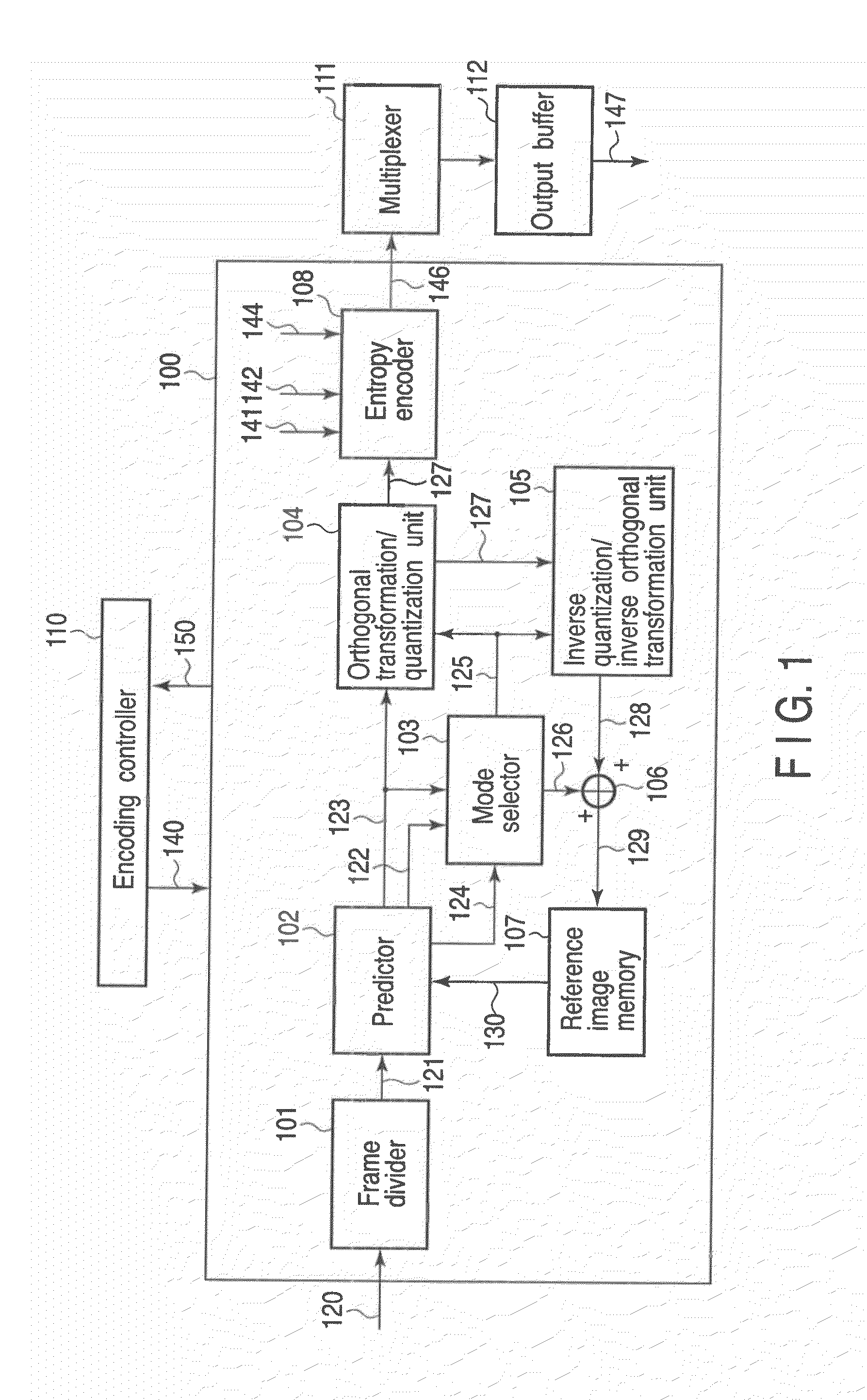
[0345]As another example, a plurality of reliability candidates of prediction modes in the bidirectional prediction may be prepared in units of blocks and switched in units of the blocks. A concrete syntax configuration is shown in FIG. 43. The configuration of the macro-block prediction syntax shown in FIG. 34 is replaced with the configuration shown in FIG. 43. Reference symbol intra4×4_bi_pred_weight_mode shown in FIG. 43 is data representing which reliability candidate is used for the 4×4 pixel blocks. For example, when the intra4×4_bi_pred_weight mode is 0, a Gaussian distribution is allocated. When the intra4×4_bi_pred_weight_mode is 1, a Laplace distribution is allocated. When the intra4×4_bi_pred_weight_mode is 2, a fixed value is allocated. As another distribution, a linear model or an M-order function (M≧1) can be replaced.

[0346]FIGS. 44, 45, 46, 47, and 48 show still another example of a syntax structure used in the image encoder 100. Pieces of syntax in...

second embodiment

Syntax Structure

[0450]FIGS. 70, 71, 72, 73, and 74 show still another examples of the structure of the syntax used in the image encoder 100. The syntax information required in the examples includes the sequence parameter set syntax 202, the picture parameter set syntax 203, the slice header syntax 205, and the macro-block layer syntax 208 in FIG. 32. The syntaxes shown in FIGS. 70, 71, 72, 73, and 74 are added to the syntax structure of the first example. The syntaxes will be described below.

[0451]Reference symbol block_order_in_seq_flag shown in the sequence parameter set syntax in FIG. 70 denotes a flag representing whether switching of prediction orders is made possible in a sequence. When the flag block_order_in_seq_flag is TRUE, the prediction orders can be switched in the sequence. On the other hand, when the flag block—order—in_seq_flag is FALSE, the prediction orders cannot be switched in the sequence. Reference symbol block_order_in_pic_flag in the picture parameter set syn...

third embodiment

f Syntax Structure

[0488]FIGS. 29, 30, 31, 32, 33, and 34 show other examples related to syntax structures related to the image decoding apparatus. Since the explanations of the syntaxes are the same as those in the image encoding apparatus, a description thereof will be omitted. The syntaxes are separated from bit streams and decoded to obtain information. Furthermore, the syntaxes may be switched depending on activity information such as correlation or variance of pixels in a decoded adjacent block. In this case, by using the same logic as that on the encoding side, the same information of the syntaxes as that in the encoding is shown. For this reason, separating and decoding processes from an encoding bit stream are not necessary.

[0489]According to one embodiment of the present invention, since the number of usable prediction modes can be selected, for example, bidirectional prediction which calculates prediction signals obtained in a plurality of prediction modes in units of pixe...


PUM


Abstract

An image encoding apparatus includes a multidirectional predicting unit configured to predict a plurality of pixel blocks by using an encoded pixel as a reference pixel according to a plurality of prediction modes having different prediction directions to generate a plurality of first prediction signals corresponding to the pixel blocks obtained by dividing a frame of an input image signal a setting unit configured to set a weighting factor depending on the prediction directions of the plurality of prediction modes and a spatial distance between a prediction pixel in the pixel block and the reference pixel, a weighted average unit configured to calculate a weighted average of the plurality of first prediction signals according to the weighting factor to generate one second prediction signal corresponding to the pixel blocks, and an encoding unit configured to encode a prediction residual error signal representing a difference between an image signal of the pixel block and at least the second prediction signal to generate encoded data.

Description

TECHNICAL FIELD [0001]The present invention relates to a method and apparatus for encoding and decoding a moving or a still image.BACKGROUND ART [0002]In recent years, an image encoding method the encoding efficiency of which is considerably improved is recommended as ITU-T Rec.H.264 and ISO / IEC 14496-10 (to be referred to as H.264 hereinafter) in cooperation with ITU-T and ISO / IEC. In an encoding scheme such as ISO / IEC MPEG-1, 2, and 4, ITU-T H.261, and H.263, intra-frame prediction in a frequency region (DCT coefficient) after orthogonal transformation is performed to reduce a code amount of a transformation coefficient. In contrast to this, directional prediction (see Greg Conklin, “New Intra Prediction Modes”, ITU-T Q.6 / SG16 VCEG, VCEG-N54, September 2001) is employed to realize prediction efficiency higher than that of intra-frame prediction in ISO / IEC MPEG-1, 2 and 4.[0003]In an H. 264 high profile, intra-frame prediction schemes of three types are regulated to a luminance sig...

Claims


Application Information

Patent Timeline
Patent Type & Authority Applications(United States)
IPC IPC(8): H04N7/26
CPCH04N19/105H04N19/176H04N19/182H04N19/593H04N19/11H04N19/61
Inventor SHIODERA, TAICHIROTANIZAWA, AKIYUKICHUJOH, TAKESHI
Owner KK TOSHIBA
Why Eureka
Try Eureka