Method for making a rivet and rivet obtained by said method

a technology of rivets and methods, applied in the field of rivets, can solve the problems of poor fatigue strength of rivets, increased cost of manufacturing rivets, and machining operations that increase the cost of rivet manufacturing,

Active Publication Date: 2010-05-13
ERIS
View PDF13 Cites 8 Cited by
  • Summary
  • Abstract
  • Description
  • Claims
  • Application Information

AI Technical Summary

Benefits of technology

[0007]In light of this fact, the applicants have carried out research aiming to reduce the cost of manufacturing these rivets while optimising the technical qualities.
[0014]By proposing an embodiment that does not require a machining operation for this portion of the rivet, the applicants have designed a method reducing the costs of manufacturing the rivet. Furthermore, such a method remains in the continuity of the cold heading operations participating in the manufacturing of the rivet and preceding the operations of carrying out the groove and the tube.
[0015]This characteristic is particularly advantageous in that it guarantees the fibre formation of the material and improves the metallurgical state of the rivet. This method further allows the size of the grains to be refined.

Problems solved by technology

This rivet nevertheless has the disadvantage of requiring a machining of its external surface in order to arrange said peripheral groove and in order to create said docking surface.
This machining operation increases the cost of manufacturing the rivet while modifying its technical characteristics.
Indeed, although the rivet is preformed by a cold heading technique the carrying out of such a groove is implemented by machining which has for effect to break the fibres of the metal which can contribute to a poor fatigue strength of the rivet.

Method used


Image

  • Method for making a rivet and rivet obtained by said method
  • Method for making a rivet and rivet obtained by said method
  • Method for making a rivet and rivet obtained by said method

Examples


Embodiment Construction

[0007]In light of this fact, the applicants have carried out research aiming to reduce the cost of manufacturing these rivets while optimising the technical qualities.

[0008]This research has resulted in the designing of a method for manufacturing rivet that is particularly advantageous, resolving the problems of prior art.

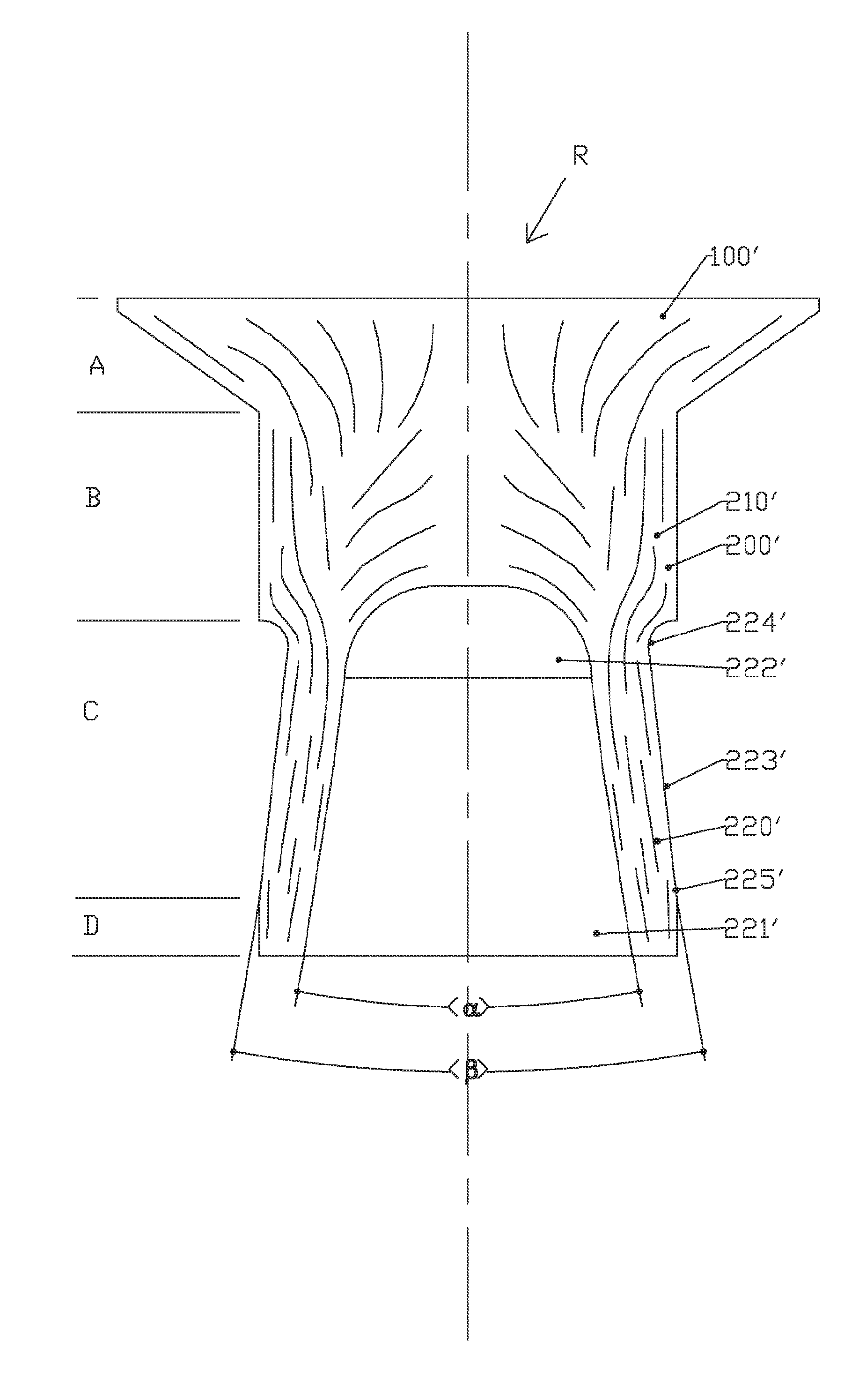
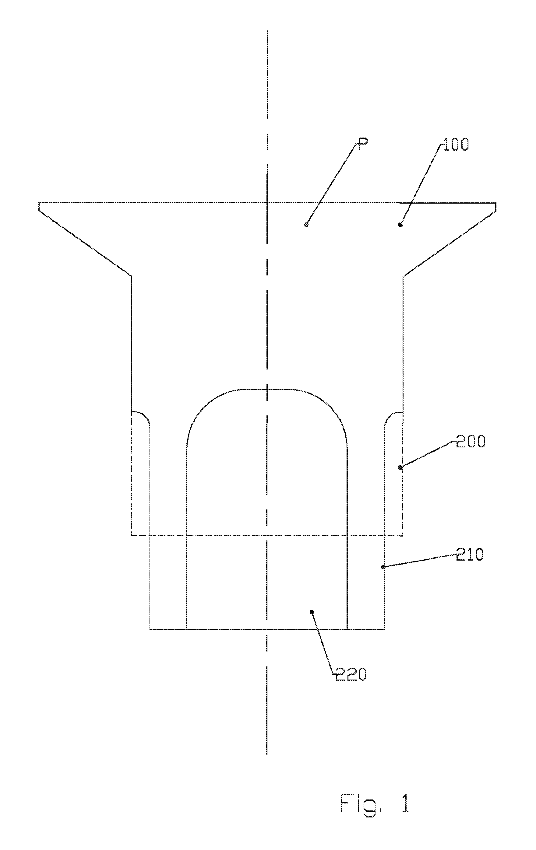
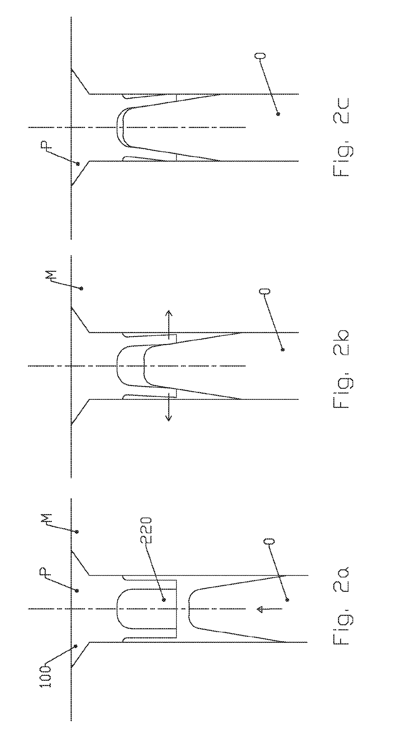
[0009]This method for manufacturing a rivet is of the type of that comprising by deformation of the material of a substantial cylindrical metal section, the preformation operations of a countersunk head at the end of a rod and is remarkable in that it comprises the carrying out by deformation of the material (cold heading) the following operations:[0010]creation of a portion with less diameter starting at the free end,[0011]creation of a substantially cylindrical hollow core in order to form a tubular portion,[0012]preformation as a truncated cone of the hollow core,[0013]preformation as a truncated cone of the external surface of less diameter.

[0014]By proposing a...


PUM

PropertyMeasurementUnit
angleaaaaaaaaaa
angleaaaaaaaaaa
angleaaaaaaaaaa

Abstract

The invention relates to a method for making a rivet (R), of the type comprising, by deformation of the material of a substantially cylindrical metal segment, the operations of preforming a milled head (100) at the end of a rod (200), characterised in that it comprises, by deformation of the material (cold stamping) the following operations: creating a portion with a lower diameter (210) from the free end; creating a substantially cylindrical hollow core (220) for forming a tubular portion; preforming the hollow core (220) as a truncated cone; performing the lower diameter outer surface as a truncated cone. The invention also relates to the rivet obtained by said method.

Description

FIELD OF THE INVENTION[0001]The invention relates to the manufacturing of rivets and in particular the adaptations making it possible to simplify the methods of manufacturing while optimising the technical characteristics of the latter.DESCRIPTION OF PRIOR ART[0002]Semi-tubular rivets exist in prior art of the type of those that include a preformed head and a rod provided with an axial drilling in order to form a tubular portion opposite the preformed head.[0003]These rivets have the advantage of being particularly adapted for the carrying out of the assembly of parts made of soft or fragile materials in particular synthetic materials such as composite material.[0004]One of these rivets described in patent FR 2587421 has for specificity to be arranged with a peripheral groove on the external surface of the rod on the tubular portion of the latter. A docking surface is preserved on said external surface at the end of the rod. This peripheral groove thus prevents the contact of this p...

Claims


Application Information

Patent Timeline
Patent Type & Authority Applications(United States)
IPC IPC(8): F16B19/08B21K1/60
CPCB21J15/046F16B19/10B21K1/60B21J15/147B21J15/04
Inventor AURIOL, JEAN-MARC
Owner ERIS
Why Eureka
Try Eureka