Reciprocating pump

a technology of reciprocating pump and rotating shaft, which is applied in the direction of machines/engines, liquid fuel engines, positive displacement liquid engines, etc., can solve the problems of difficult easy wear of the bearings, etc., and achieve the effect of improving the stabilization and smooth movement of the moving body, prolonging the life period, and increasing the portion of the slide bearings

Active Publication Date: 2010-05-13
NIPPON PILLAR PACKING CO LTD
View PDF14 Cites 10 Cited by
  • Summary
  • Abstract
  • Description
  • Claims
  • Application Information

AI Technical Summary

Benefits of technology

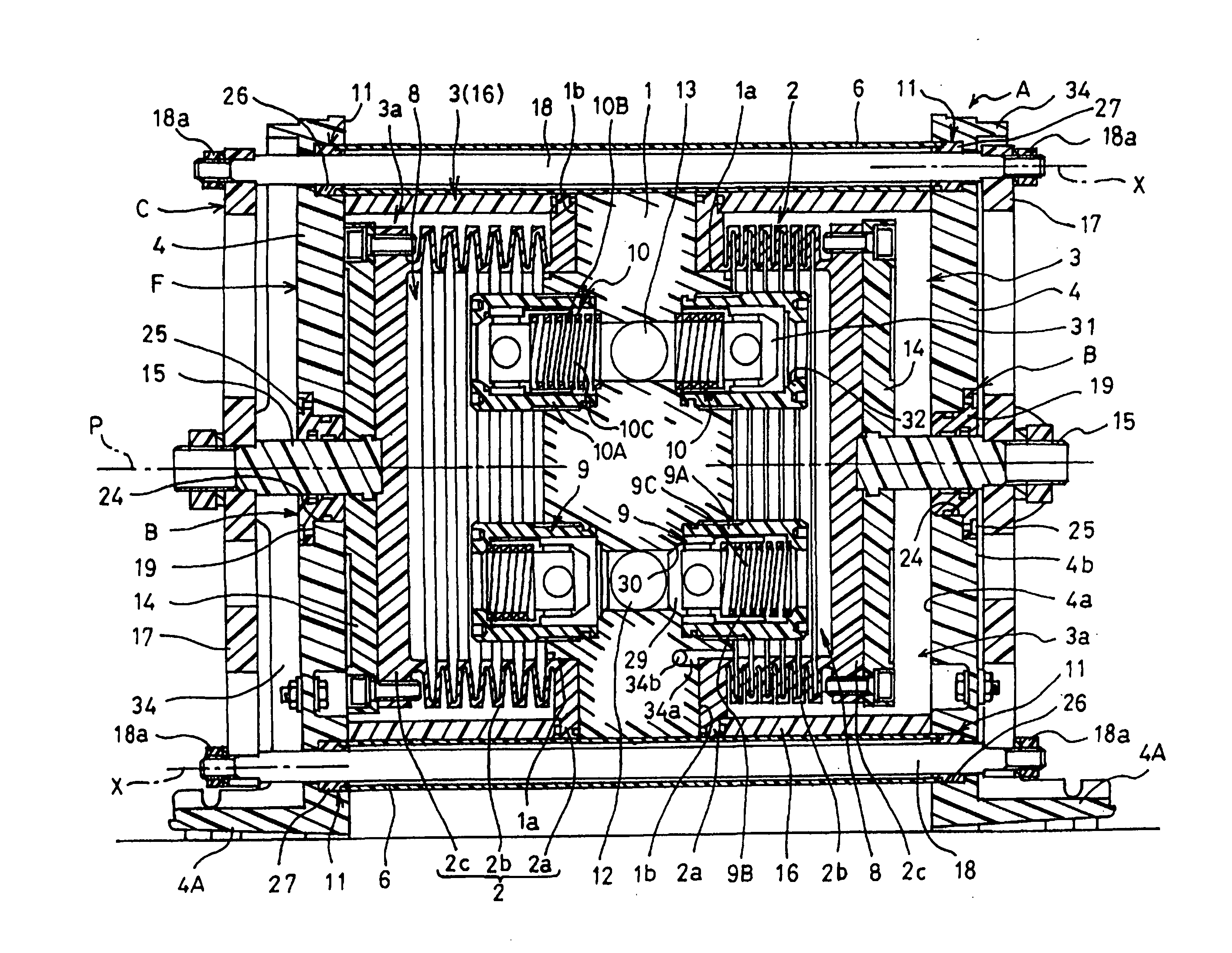
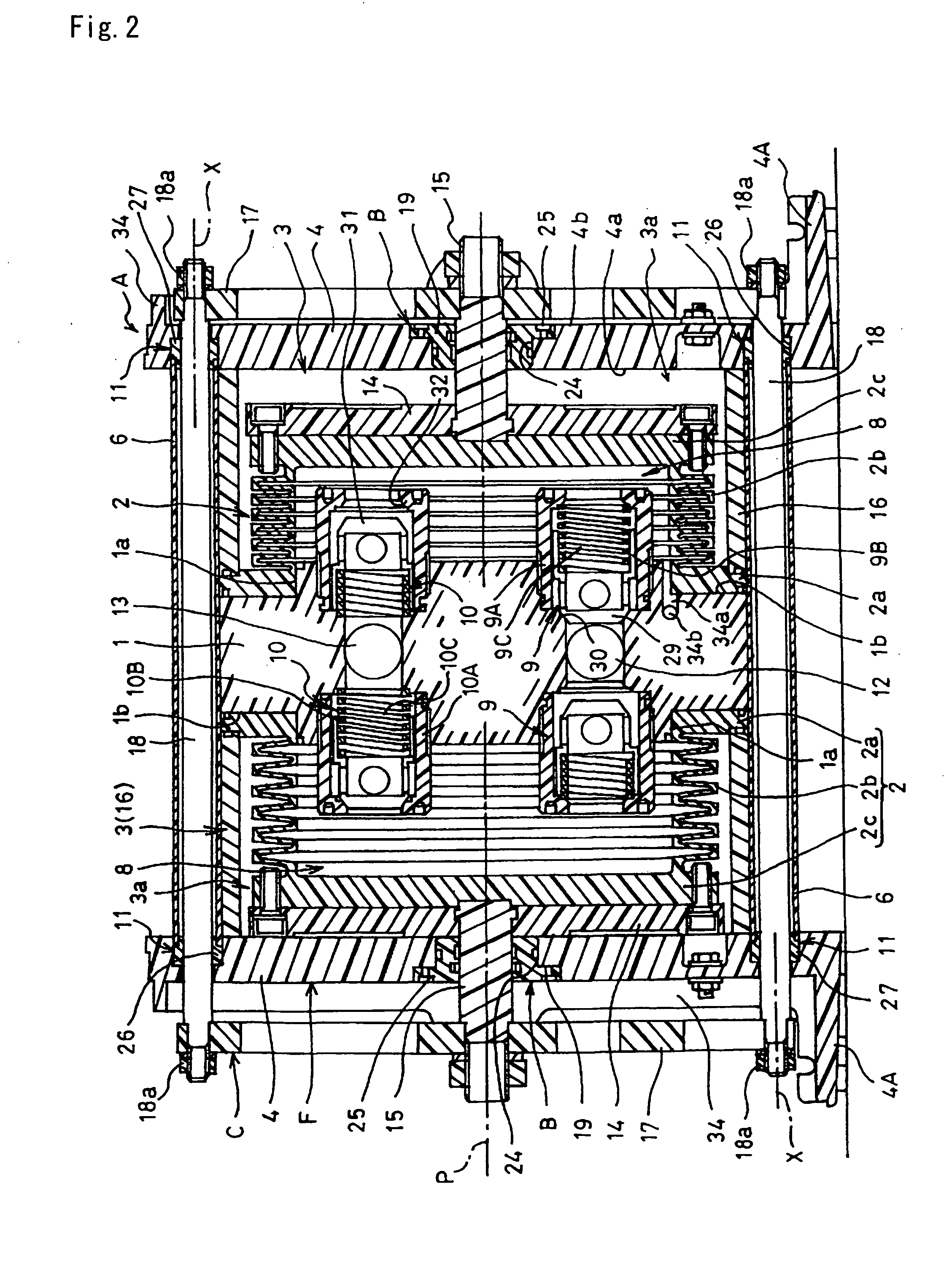
[0015]According to the invention set forth in claim 1, in a moving body configured by the pair of pump shafts which are attached to tip end portions of the bellows, the pair of connecting plates, the plural connecting rods, and the like, not only the portions of the pump shafts, but also the both end portions of the connecting rods are slidably supported. Therefore, the load burden, which is concentrated to the pump shafts in the prior art, is distributed also to bearing portions of the connecting rods, and hence it is possible to provide a reciprocating pump in which wear of slide bearings can be suppressed, and the life period can be prolonged. In the moving body which is a relatively large structure, furthermore, portions of slide bearings are remarkably increased. Therefore, also the stabilization and smoothness of movement of the moving body can be improved, and also an advantage that the pump can be operated more smoothly and lightly can be obtained.
[0016]According to the invention set forth in claim 2, the slide bearings of the connecting rods are formed into a slit cylindrical shape in which a section is formed into a C-like shape, and therefore it is possible to provide a reciprocating pump in which, even when the slide bearings and the connection rods are expanded or contracted by a change of the ambient temperature, sliding heat, or the like, the slide bearings are easily expandingly or contractingly displaced in the circumferential direction, so that the expansion or the contraction can be absorbed, and an excellent sliding supporting state between the connection rods and the slide bearings can be maintained.
[0017]The invention set forth in claim 3 has the structure where the cover cylinder which surrounds the connecting rods in order to protect them is fitted and supported by the slide bearings, i.e., the structure where the cover cylinder is fitted through one component (slide bearings). As compared with the case where a cover cylinder is fitted through two components (pump flanges, and slide bearings), such as the case where a cover cylinder is fitted and supported by pump flanges, therefore, there are advantages such as that the cover cylinder can be assembled with a higher dimensional accuracy, and that a cylinder having a smaller diameter which is closer to the diameter of the connection rods can be used. In this case, when, as in claim 4, the slide bearings are formed into a stepped shape having: a small-diameter portion onto which the cover cylinder is fitted; and a large-diameter portion which is fitted into the pump flange, there are additional advantages such as that the cover cylinder can be made thinner, and that the inner diameter of holes of the pump flanges and for attaching the slide bearings can be formed as a constant diameter which is economical and easily produced, and which does not form a step.
[0018]In the configuration where the cover cylinder is fitted and supported by the slide bearings, when the slide bearings are to be attached to or detached from the pump flanges in order to perform maintenance such as maintenance check or replacement of the slide bearings, operations of attaching and detaching the slide bearings with respect to the pump flanges, and those of attaching and detaching the slide bearings and the cover cylinder in a state of a small structure which is configured by the slide bearing and the cover cylinder, and which is detached from the pump flanges are conducted. This is cumbersome because, in the case where the cover cylinder is fitted and supported with respect to the pump flanges, for example, both the operations of attaching and detaching the cover cylinder with respect to the pump flanges, and those of attaching and detaching the slide bearings with respect to the pump flanges must be conducted in the reciprocating pump. In the invention set forth in claim 3, there is a further advantage that the cumbersome operation is improved and the attaching and detaching operations can be facilitated.
[0019]According to the invention set forth in claim 5, although described in detail in the paragraph of embodiments, the bearing mechanisms which slidably support the pump shafts can be detached from the pump flanges toward the connecting plates, i.e., toward the outside. In maintenance check or replacement of bearings means or sealing means for the pump shafts, therefore, only a work of detaching the connecting plates from the connecting rods is requested in addition to operations of detaching and attaching the bearing mechanisms. Therefore, an advantage is obtained that, as compared with a conventional reciprocating pump in which also pump flanges must be detached and attached in addition to connecting plates, the maintenance property of the slide supporting structure for the pump shafts can be improved.
[0020]According to the invention set forth in claim 6, it is possible to provide a bellows reciprocating pump which has the above-described effects of any one of claims 1 to 5, and which is easy to use and improved.

Problems solved by technology

Therefore, the load against the pump shaft bearings 23a, 23b equipped in the pump flanges is large, so that the bearings tend to be easily worn, and there is a possibility that it is difficult to smoothly perform the slide movement of the moving body.

Method used


Image

  • Reciprocating pump
  • Reciprocating pump
  • Reciprocating pump

Examples


example 1

[0057]As shown in FIGS. 1 to 3, the reciprocating pump A is a large-capacity reciprocating pump which has a structure similar to that where one pair of bellows pumps are combined with each other in a back-to-back configuration, and in which the discharge amount per unit time can be large. The reciprocating pump A is configured to have: a pump body 1 which is made of a fluororesin (PTFE) or the like, and which is in the middle in the lateral direction; a pair of bellows (an example of a diaphragm) 2, 2 which are placed in the right and left sides of the pump body 1, and which are made of a fluororesin (PTFE) or the like; a pair of air cylinders 3, 3; a pair of pump flanges 4, 4 which are made of a stainless material (SUS304) or the like; a total of four through bolt nuts 5; a total of four cover cylinders 6, 6; a pair of end covers 7, 7; and the like. FIG. 3 is a side view of a state where the end covers 7 are removed.

[0058]Hereinafter, the pumping function will be briefly described....


PUM


Abstract

The structure is improved so that a bearing is disposed in a place other than pump shafts, thereby improving the smoothness of the slide movement of a moving body which is a large structure, and the durability of slide supporting means (bearings or the like) for it. In a reciprocating pump having: a pump body 1 including a suction path 12 and discharge path 13 for a fluid; a pair of diaphragms 2 which are airtightly fixed to both end portions of the pump body; pump shafts 15 which are attached to tip end portions of the diaphragms 2; a pair of pump flanges 4 which slidably support the pump shafts 15, and which are integrated with the pump body 1 through connection bodies 16 that are placed outside the diaphragms 2; connecting rods 18 which connect connecting plates 17 attached to projecting tip-end portions 15B that are projected from the pump flanges 4 in the pump shafts 15, to each other in a state where the connecting rods are passed through the pump flanges 4 to be placed outside the diaphragms 2; and a cover cylinder 6 which is disposed between the pair of pump flanges 4, and which surrounds the connecting rods 18, the connecting rods 18 are slidably supported through slide bearings 27 which are supported by the pump flanges 4.

Description

TECHNICAL FIELD[0001]The present invention relates to a reciprocating pump which is a bellows pump, a diaphragm pump, or the like, and which is suitable as liquid transporting means for pure water or medical solution and to be used in equipment or apparatus for producing a semiconductor or liquid crystal.BACKGROUND ART[0002]A reciprocating pump of this kind is a large-capacity (the discharge amount per unit time is large) reciprocating pump in which one pair of diaphragms such as bellows are mounted in a back-to-back configuration in the pump body, and tip end portions of the diaphragms are interlockingly connected to each other by connecting rods which are placed in the lateral outsides so as to detour around the diaphragms, whereby the pair of diaphragms are complementarily expanded and contracted to continuously perform pumping. For example, the pump disclosed in Patent Reference 1 is known.[0003]As shown in FIG. 2 of Patent Reference 1, namely, in order to complementarily expand...

Claims


Application Information

Patent Timeline
Patent Type & Authority Applications(United States)
IPC IPC(8): F04B45/04
CPCF04B43/1136F04B43/084F04B43/086F04B53/10F05B2210/11Y10S417/00
Inventor MASUDA, AKIHIROMORI, MITSUO
Owner NIPPON PILLAR PACKING CO LTD
Why Eureka
Try Eureka