Scanning endoscope, scanning endoscope processor, and scanning endoscope apparatus

a technology of scanning endoscope and scanning endoscope, which is applied in the field of scanning endoscope, scanning endoscope processor, and scanning endoscope apparatus, can solve the problems of difficult circulation of emission end and increase the radius of circulation, and achieve the effect of reducing the amount of distortion

Inactive Publication Date: 2010-05-13
HOYA CORP
View PDF16 Cites 34 Cited by
  • Summary
  • Abstract
  • Description
  • Claims
  • Application Information

AI Technical Summary

Benefits of technology

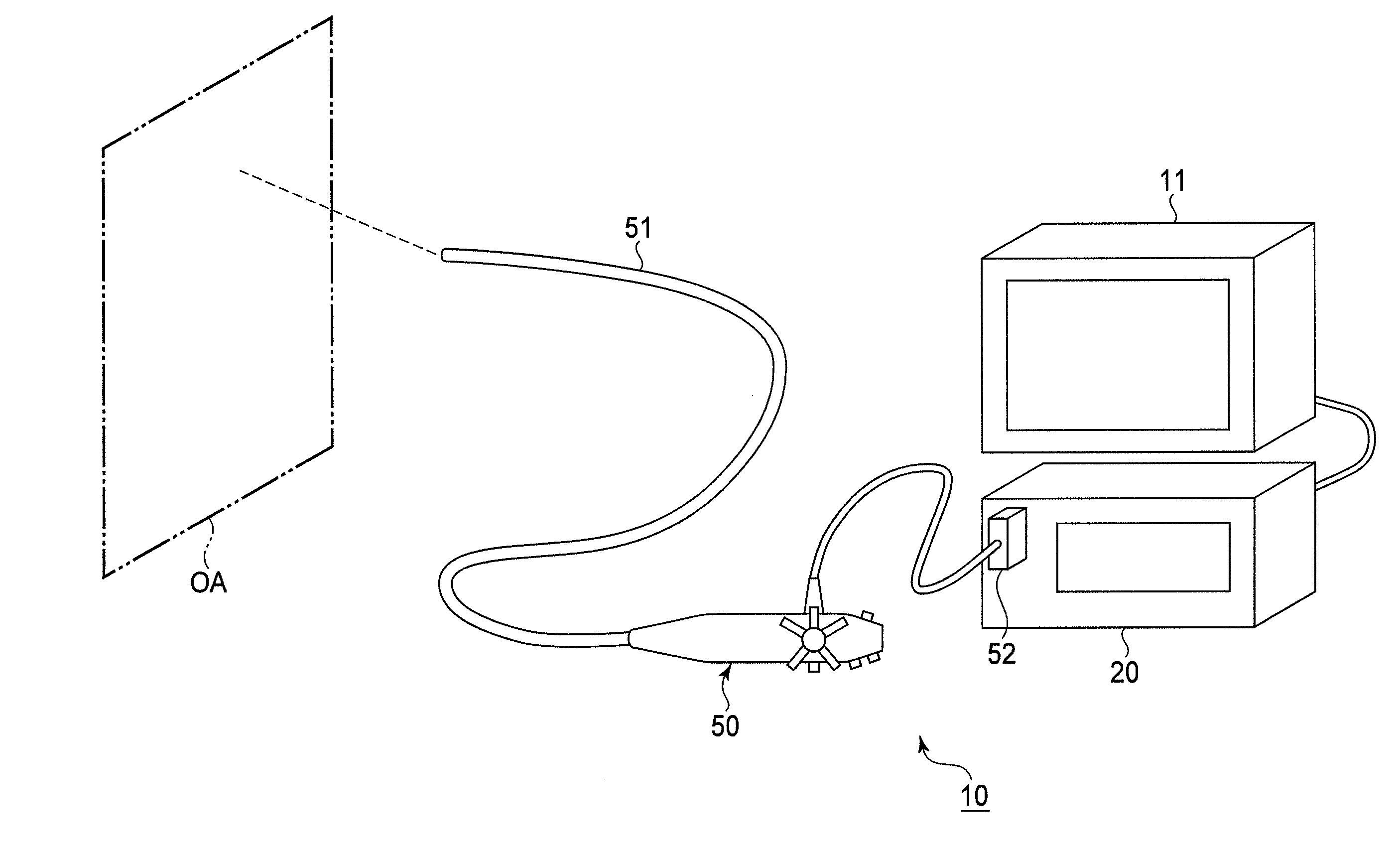
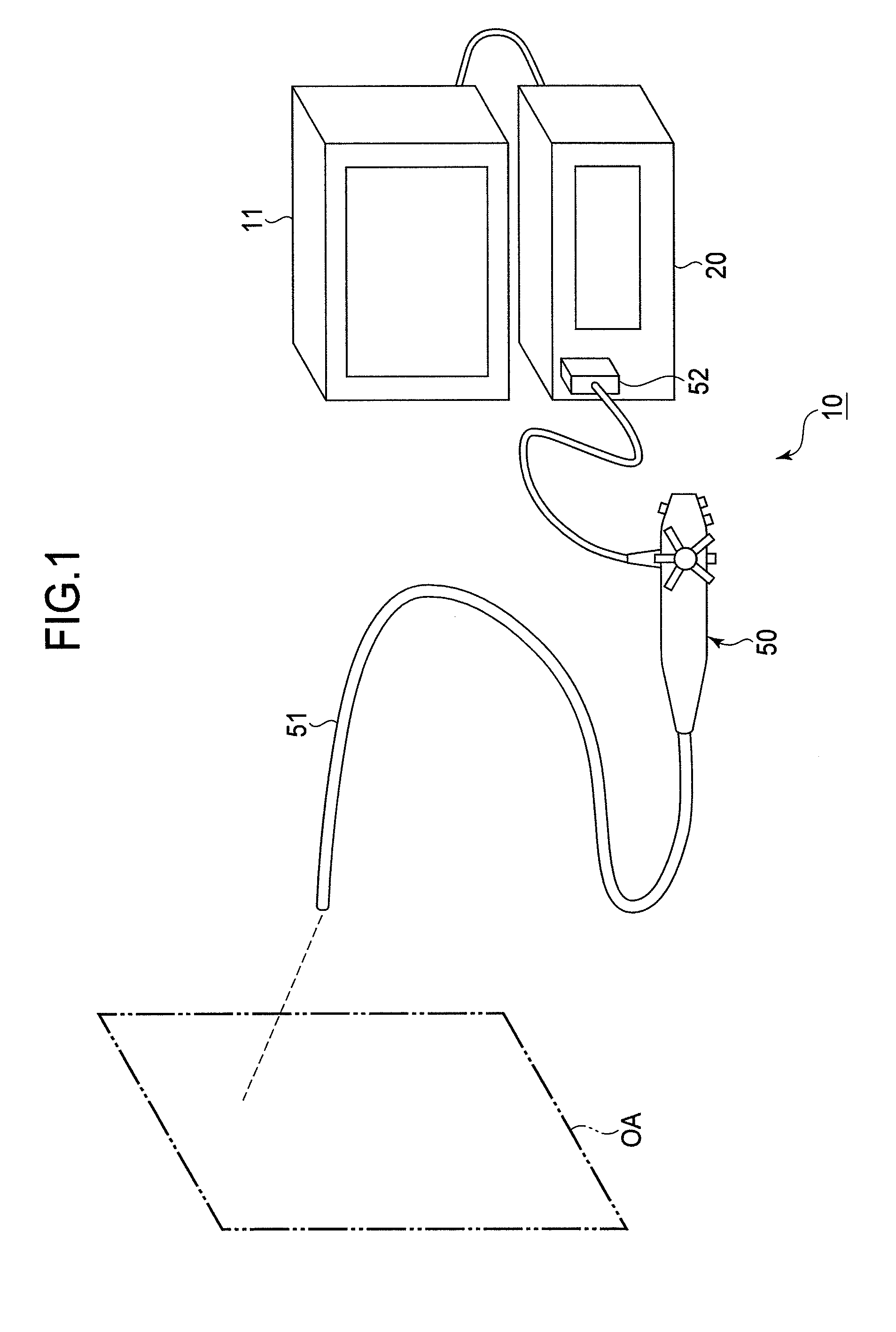
[0007]Therefore, an object of the present invention is to provide a scanning endoscope that scans an observation area with light along a spiral scanning course while reducing the amount of distortion that appears in a reproduced image near the point corresponding to the center of the spiral course.

Problems solved by technology

However, it is difficult to circulate the emission end and increase the radius of the circulation when the emission end is near the center of the spiral course.

Method used


Image

  • Scanning endoscope, scanning endoscope processor, and scanning endoscope apparatus
  • Scanning endoscope, scanning endoscope processor, and scanning endoscope apparatus
  • Scanning endoscope, scanning endoscope processor, and scanning endoscope apparatus

Examples


first embodiment

[0091]In the above first embodiment, an image of the entire observation area can be produced without using the white laser beam emitted from the emission end that is moved near the center of the spiral course. By avoiding using the white laser beam emitted from the emission end that is moved near the center of the spiral course, distortion in the produced image will be reduced.

[0092]Next, a scanning endoscope and a scanning endoscope processor of the second embodiment are explained. The primary difference between the second embodiment and the first embodiment is the structure of the second mirror. In addition, in the second embodiment the position of the emission end of the illumination fiber is estimated on the basis of optical information gained from the scanning endoscope, unlike in the first embodiment. The second embodiment is explained mainly with reference to the structures that differ from those of the first embodiment. Here, the same index numbers are used for the structure...

second embodiment

[0126]In the above second embodiment, an image of the entire observation area can be produced without using the white laser beam emitted from the emission end that is moved near the center of the spiral course. By avoiding using the white laser beam, distortion in the produced image will be reduced.

[0127]In addition, in the above second embodiment, it is possible to detect the direction in which the emission end of the illumination fiber 53 inclines. Accordingly, the time required to return the emission end of the illumination fiber 53 to the first circumference, from the start of the braking period, can be shortened.

[0128]In addition, the accuracy of the estimation of the points where the white laser beam is shined is improved because the point is estimated using the direction in which the emission end of the illumination fiber 53 inclines. It is possible to reduce the influence of the distortion appearing in the displayed image by improving the accuracy of the estimation.

[0129]The...


PUM


Abstract

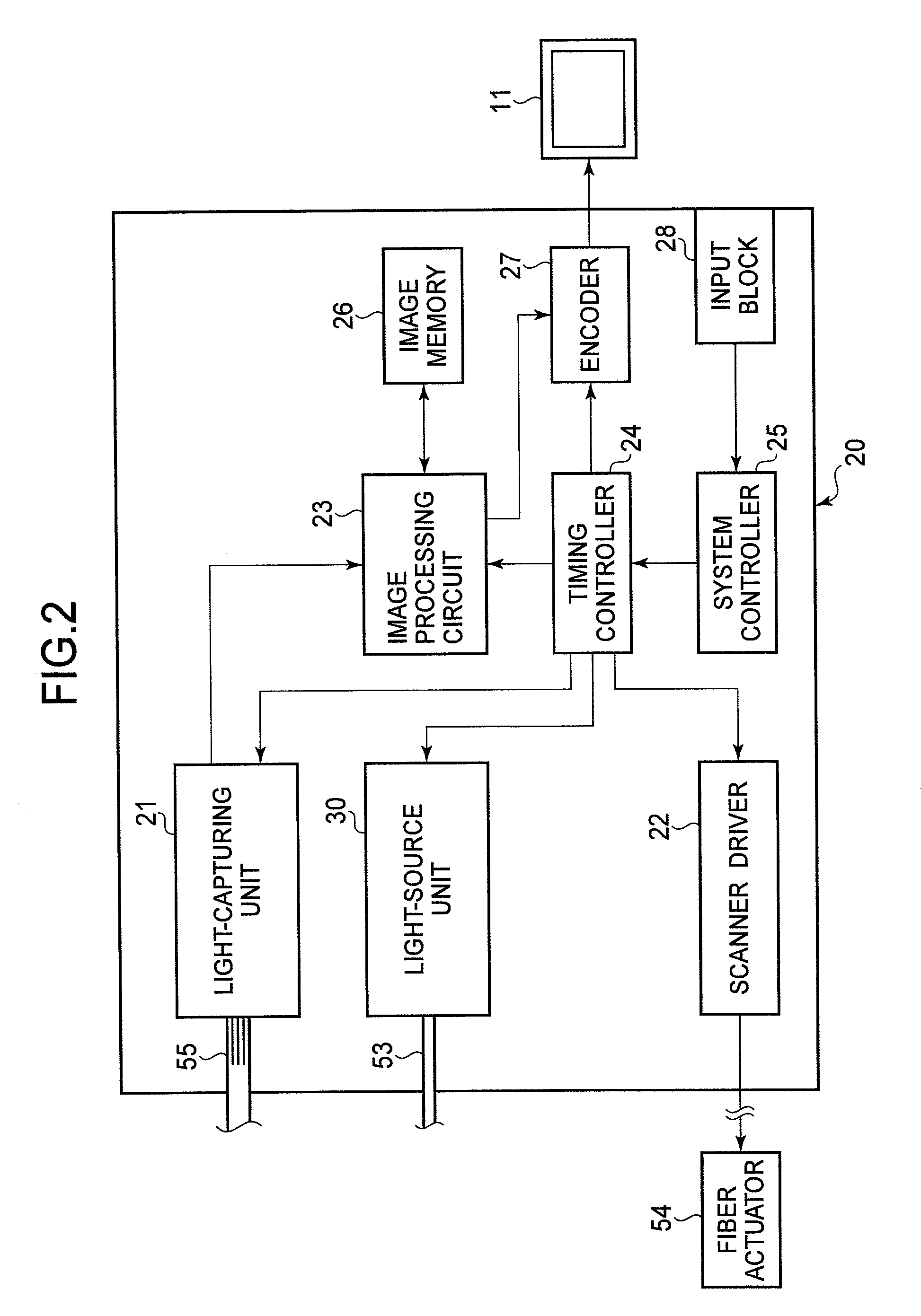
A scanning endoscope comprising a first transmitter, an actuator, a first mirror, and a second mirror, is provided. The first transmitter emits a beam of radiant light from an emission end. The actuator moves the emission end along a spiral course. The first mirror is arranged from the emission end toward a first direction. The first mirror comprises a first reflection surface around the first direction. The first reflection surface reflects the radiant light emitted from the first transmitter. The second mirror is arranged around the first reflection surface. The second mirror comprises a second reflection surface. The second reflection surface reflects the radiant light reflected by the first mirror in a direction that includes the first direction as a positive vector toward any points on the first line.

Description

BACKGROUND OF THE INVENTION[0001]1. Field of the Invention[0002]The present invention relates to reducing distortion appearing around the center of a spiral scanning course when using a scanning endoscope that scans a subject with illumination light along the spiral scanning course.[0003]2. Description of the Related Art[0004]A scanning endoscope, which photographs and / or films an optical image of an observation area by scanning the observation area with light shined on a minute point in the area and successively capturing reflected light at the illuminated points, is known. In a general scanning endoscope, light for illumination is transmitted through an optical fiber from a stationary incident end to a movable emission end and a scanning operation is carried out by successively moving the emission end of the optical fiber.[0005]For the purpose of quick and stable scanning, Japanese Patent No. 3943927 discloses that the emission end of the optical fiber is moved along a spiral cour...

Claims


Application Information

Patent Timeline
Patent Type & Authority Applications(United States)
IPC IPC(8): A61B1/06
CPCA61B1/0008A61B1/00165A61B1/00172H04N5/2256G02B23/2423G02B26/103G02B27/141A61B1/04H04N23/56
Inventor SUGIMOTO, HIDEO
Owner HOYA CORP
Why Eureka
Try Eureka