Baseplate for a ring laser gyroscope

a laser gyroscope and base plate technology, applied in the direction of speed measurement using gyroscopic effects, instruments, surveying and navigation, etc., can solve the problems of mirrors, laser optical path out of alignment, and mirror misalignment, so as to improve the distortion characteristics

Active Publication Date: 2008-04-03
HONEYWELL INT INC
View PDF17 Cites 3 Cited by
  • Summary
  • Abstract
  • Description
  • Claims
  • Application Information

AI Technical Summary

Benefits of technology

[0010]As will be readily appreciated from the foregoing summary, the invention provides a baseplate with openings that improve the distortion characteristics by permitting strains in the baseplate to be more uniformly distributed.

Problems solved by technology

This distortion in the baseplate may be significant enough to cause the mirror transducer substrate assembly, and thus the mirrors, to be out of alignment with a laser optical path within the laser block.
In addition or alternatively, this distortion, when combined with the distortion resulting from bonding the PLC driver with the mirror transducer substrate assembly, may cause misalignment of the mirrors.
Problems can arise when this assembly is removed from the block such as the optical contact area warping.
When this situation occurs it requires either a re-polish of the optical contact area (with driver attached) or driver removal which results in scrapping the driver assembly.
Re-polish of the mirror with a transducer bonded on to achieve a optical contactable flat interface presents the problem of an out of flat mirror once the PLC driver is removed and the mirror is re-used.

Method used


Image

  • Baseplate for a ring laser gyroscope
  • Baseplate for a ring laser gyroscope
  • Baseplate for a ring laser gyroscope

Examples


Embodiment Construction

[0019]In the following description, certain specific details are set forth in order to provide a thorough understanding of various embodiments of the invention. In other instances, well-known structures and methods associated with ring laser gyroscopes (RLGs) and methods of making and / or assembling the same may not be shown or described in detail to avoid unnecessarily obscuring descriptions of the embodiments of the invention.

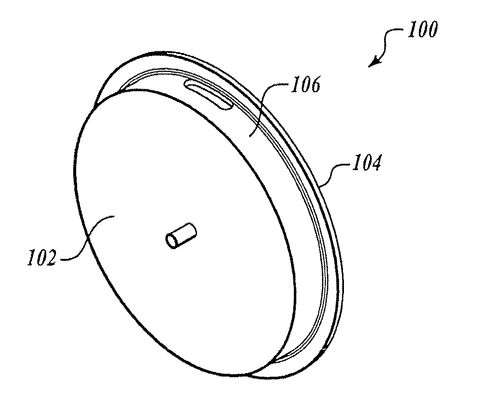
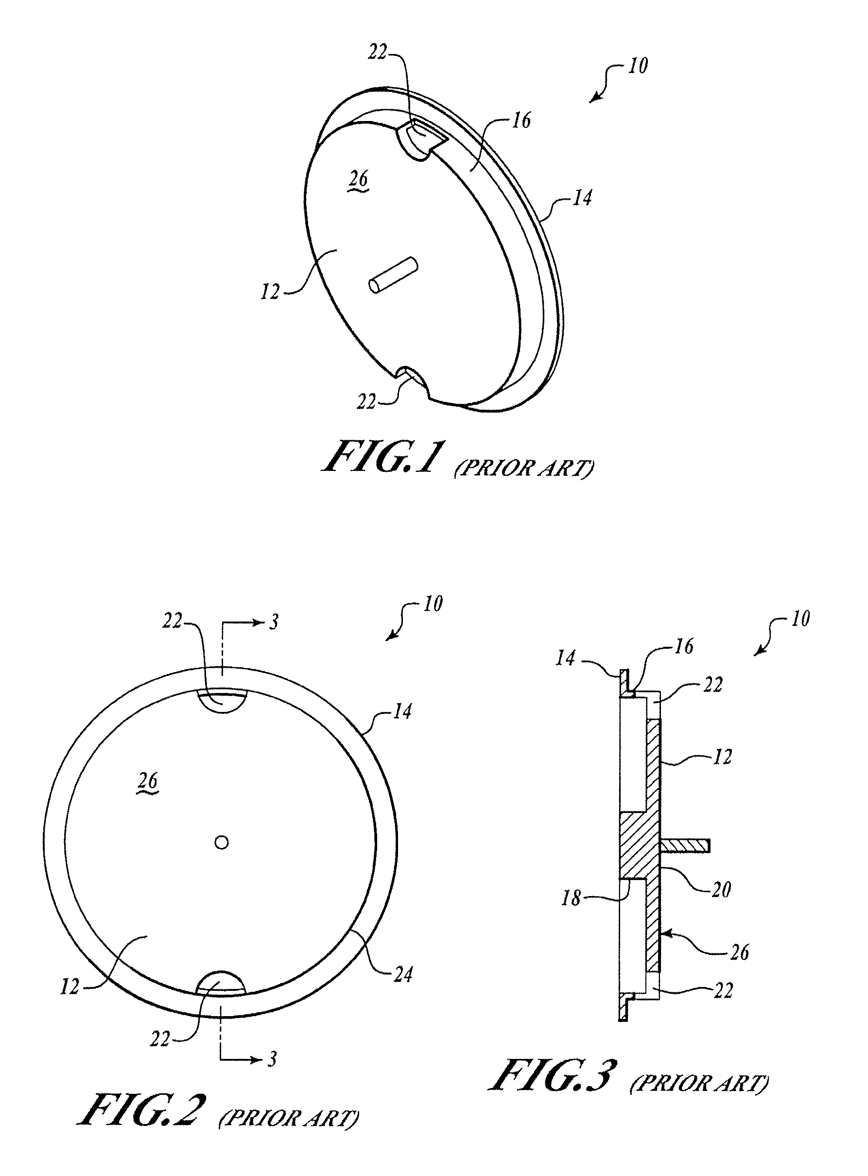
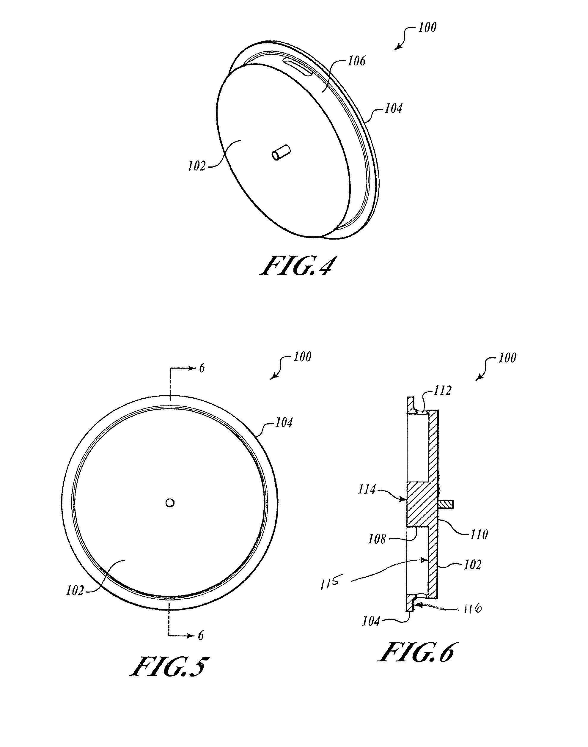
[0020]The following description generally relates to a baseplate of a having reduced distortion or deformation characteristics. As is generally known in the art and described in U.S. Pat. No. 5,420,685, the RLG includes a laser block, a path length control (PLC) driver, and a mirror transducer substrate assembly. The PLC driver includes a baseplate, a number of piezoelectric elements, and a conductive network. The mirror transducer substrate assembly includes a transducer block and a reflective device affixed thereto. The mirror transducer substrate assembly i...


PUM


Abstract

A path length control driver for a ring laser gyroscope includes a baseplate, a number of piezoelectric elements, and electrodes. The baseplate includes openings selectively sized and located on the baseplate for reducing distortion thereof during thermal or other mechanical loading. The baseplate includes a central hub extending from a central portion of an actuator plate, which comprises an annular diaphragm member. The baseplate further includes an outer rim or sidewall coupled to the actuator plate and a baseplate flange extending from the sidewall. In one embodiment, a portion of the baseplate flange is attached to a mirror transducer substrate assembly. The mirror transducer substrate assembly includes a reflective device, such as a mirror, and a transducer block. The transducer block includes an optical contact surface onto which the mirror is affixed. The piezoelectric elements are employed to achieve a desired amount of movement of the baseplate, which in turn induces micro-movements or micro-adjustments of the mirror.

Description

BACKGROUND OF THE INVENTION[0001]A ring laser gyroscope (RLG), sometimes referred to as a ring laser angular rate sensor or short handedly referred to as a ring laser gyro, is used in navigational and guidance systems for a land, air, and / or space vehicles. The RLG utilizes laser beams traveling in opposite directions within a closed loop optical path that are directed by a plurality of reflective devices, such as mirrors. By way of example, an angular orientation of the vehicles is detected with signal processing electronics (e.g., photodiodes), which compares a frequency differential caused by different path lengths of the two beams.[0002]A conventional RLG includes a laser block, a path length control (PLC) driver, and a mirror transducer substrate assembly. The PLC driver generally includes a baseplate, piezoelectric elements, and conductive elements. The mirror transducer substrate assembly generally includes a transducer block with a reflective device, such as a mirror affixed...

Claims


Application Information

Patent Timeline
Patent Type & Authority Applications(United States)
IPC IPC(8): G01C19/66
CPCG01C19/665
Inventor BECKWITH, TIMOTHY A.BRINTZ, WILLIAM M.
Owner HONEYWELL INT INC
Why Eureka
Try Eureka