Aluminum powder metal alloying method

a technology of aluminum powder and alloying method, which is applied in the field of powder metal formulation, can solve the problems of reducing the mechanical strength of the sintered part, reducing the amount of distortion, and saving significant machining or reworking costs

Active Publication Date: 2017-01-03
SKN SINTER METALS LLC (US)
View PDF21 Cites 2 Cited by
  • Summary
  • Abstract
  • Description
  • Claims
  • Application Information

AI Technical Summary

Benefits of technology

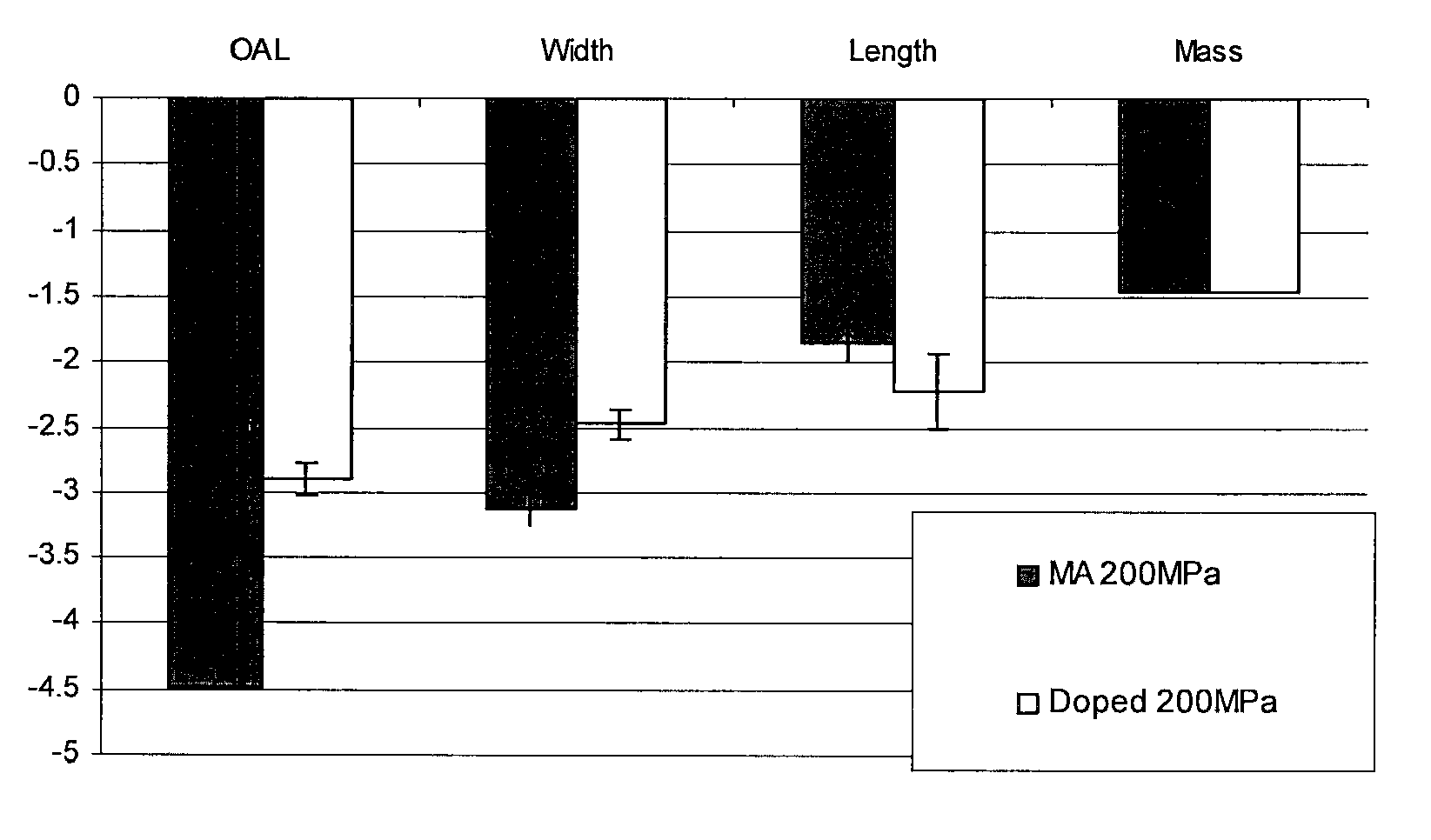
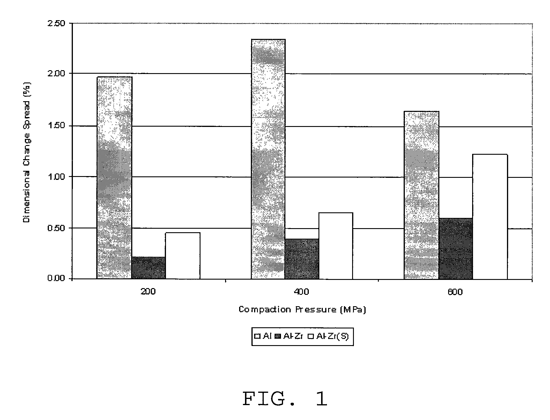
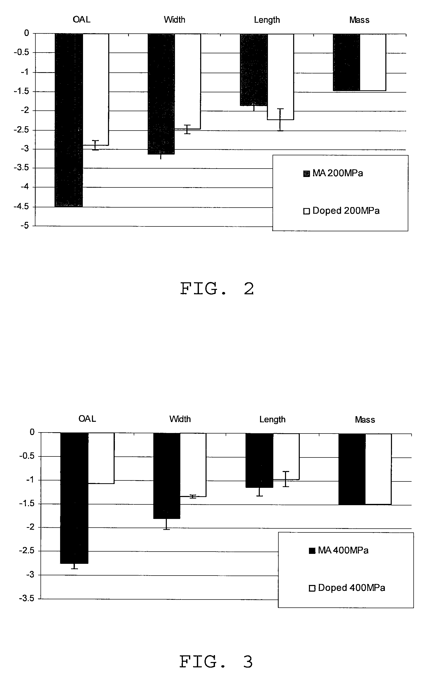
[0009]An improved aluminum powder metal, and a related method of making the powder metal, is disclosed which has reduced distortion during sintering of a part made by the powder metal. The aluminum powder metal reduces the amount of distortion at least in part, by doping the aluminum powder metal with zirconium in a relatively homogenous fashion throughout the powder metal. Further, a formulation of this powder metal composition is disclosed including an amount of tin which provides an improved Young's modulus that, surprisingly and unexpectedly, approaches the Young's modulus of a fully dense material made by casting or the like.
[0012]A powder metal part may be formed from the zirconium-doped aluminum powder metal. A quantity of zirconium in the powder metal part may be substantially equal to a quantity of zirconium found in the zirconium-doped aluminum powder metal used to form the powder metal part, meaning that little or no zirconium is added by an elemental powder or as part of a master alloy. The zirconium-doped aluminum powder metal may inhibit distortion of the powder metal part during a sintering process used to form the powder metal part. The powder metal part may include zirconium in an amount of less than 2.0 weight percent.
[0018]In some forms, the powder metal may include a percentage of fines effective to further enhance the dimensional stability of a part made from the powder metal. In one embodiment, the weight percentage of fines may exceed 10 weight percent of the powder metal.

Problems solved by technology

This dimensional accuracy can save significant expense in machining or reworking, particularly for parts having large production volumes.
Even at long sintering times, however, some voids will remain in the sintered part.
Unfortunately, for sintered parts that are less than fully dense, the mechanical strength of those sintered parts are also usually somewhat less than that of a wrought part.
This kind of anisotropic shrinkage can alter the dimensional accuracy of the as-sintered final part and, in some cases, may require that parts be reworked after sintering.

Method used


Image

  • Aluminum powder metal alloying method
  • Aluminum powder metal alloying method
  • Aluminum powder metal alloying method

Examples


Embodiment Construction

[0029]A number of powder metal samples were produced having various chemistries for comparison purposes. As a baseline system for comparison, a blend designated A36 was used. The formulation for the A36 blend is found in Table I below.

[0030]

TABLE IPowderWeight PercentageAl84.8Al—Cu (50-50)5.9Master alloyAtomized Mg1.5Sn0.6AlN5.8Licowax C1.5

The Licowax C is a lubricant material and boils off during heating. Thus, the total mass of powder for a 1 kg lot will actually exceed 1 kg because of the additional mass of the Licowax C constituent.

[0031]A modified form of the A36 powder formulation was also produced which will be referred to in this application as E36-Zr. The E36-Zr powder formulation is identical to the A36 blend, except that the aluminum powder is replaced with an air atomized zirconium-doped aluminum powder metal having 0.2% by weight zirconium. The formulation for the E36-Zr blend is found in Table II below.

[0032]

TABLE IIPowderWeight PercentageAl—0.2Zr84.8Al—Cu (50-50)5.9Ma...


PUM

PropertyMeasurementUnit
weight percentaaaaaaaaaa
Young's modulusaaaaaaaaaa
volume percentaaaaaaaaaa

Abstract

A zirconium-doped aluminum powder metal and a method of making this powder metal are disclosed. The method of making includes forming an aluminum—zirconium melt in which a zirconium content of the aluminum—zirconium melt is less than 2.0 percent by weight. The aluminum—zirconium melt then powderized to form a zirconium-doped aluminum powder metal. The powderization may occur by, for example, air atomization.

Description

CROSS-REFERENCE TO RELATED APPLICATION[0001]This application represents the national stage entry of PCT International Application No. PCT / US2011 / 054741 filed on Oct. 4, 2011, and claims the benefit of U.S. provisional patent application No. 61 / 389,512 filed on Oct. 4, 2010. The disclosure of each of these applications is hereby incorporated by reference as if set forth in their entirety herein.STATEMENT OF FEDERALLY SPONSORED RESEARCH OR DEVELOPMENT[0002]Not applicable.BACKGROUND OF THE INVENTION[0003]This disclosure relates to powder metallurgy. In particular, this disclosure relates to powder metal formulations for powder metallurgy.[0004]Powder metallurgy is an alternative to more traditional metal forming techniques such as casting. Using powder metallurgy, parts with complex geometries may be fabricated that have dimensions very close to those dimensions desired in the final part. This dimensional accuracy can save significant expense in machining or reworking, particularly for...

Claims


Application Information

Patent Timeline
Patent Type & Authority Patents(United States)
IPC IPC(8): B22F3/12B22F9/08B22F1/00C22C21/16C22C21/12C22C21/10C22C21/00C22C1/04
CPCB22F1/0003B22F3/12B22F9/082C22C1/0416C22C21/00C22C21/10C22C21/12C22C21/16B22F2998/00B22F2999/00B22F2201/02B22F2201/11B22F2201/12B22F2201/50C22C32/0063C22C32/0068B22F1/00
Inventor BISHOP, DONALD PAULHEXEMER, JR., RICHARD L.DONALDSON, IAN W.COOKE, RANDY WILLIAM
Owner SKN SINTER METALS LLC (US)
Why Eureka
Try Eureka