Stent compression tool

a compression tool and stent technology, applied in the field of stent compression tools, can solve the problems of stent separation, material tends to take a “set”, and cannot allow the installation of stents within, and achieve the effect of preventing inadvertent separation of the collar

Inactive Publication Date: 2010-05-13
ELLA CS
View PDF17 Cites 23 Cited by
  • Summary
  • Abstract
  • Description
  • Claims
  • Application Information

AI Technical Summary

Benefits of technology

[0010]The stent compression tool includes a generally tubular device having a funnel-shaped mouth at one end and a relatively narrower opening at the opposite end. The narrower end portion or sleeve includes a series of longitudinal slots to allow the sleeve to expand over the atraumatic tip of the delivery catheter assembly during the stent installation process. A sleeve retaining collar slides axially along the sleeve to preclude spreading of the sleeve segments or to allow them to spread, depending upon the collar position along the sleeve. A collar stop extends axially from the collar to prevent inadvertent separation of the collar from the tube.
[0011]The stent compression tool is used with a conventional stent delivery catheter to install the stent within the end of the catheter. The tool is initially installed over the extended atraumatic tip, i.e., a relatively large diameter and blunt tip configured to minimize puncture or other trauma to the bodily passage into which the delivery catheter is inserted, and stent carrying member of the catheter assembly, and the stent is inserted through the larger diameter funnel mouth or opening of the tool. The stent is pushed through the tool, whereupon it is compressed diametrically as it passes through the narrower sleeve portion of the tool. When a portion of the stent has extended from the narrow end or opening of the tool, the stent carrying member with its stent grip is inserted farther through the tool for the grip to engage the inner diameter of the stent and pull it back into the narrow portion of the tool.

Problems solved by technology

This can be a tedious operation, depending upon the configuration of the stent and delivery catheter.
However, a problem with many stents, and particularly those formed of biodegradable material, is that such material tends to take a “set,” i.e., to retain the physical shape and configuration to which it has been subjected, if held in that shape and configuration for long.
This characteristic does not allow such stents to be installed within the delivery catheter long before the operation.
This can be a tedious procedure, as noted above, and in any case it takes further time to carry out the stent-to-catheter installation process, with time often being critical in the performance of medical procedures.

Method used


Image

  • Stent compression tool
  • Stent compression tool
  • Stent compression tool

Examples


Embodiment Construction

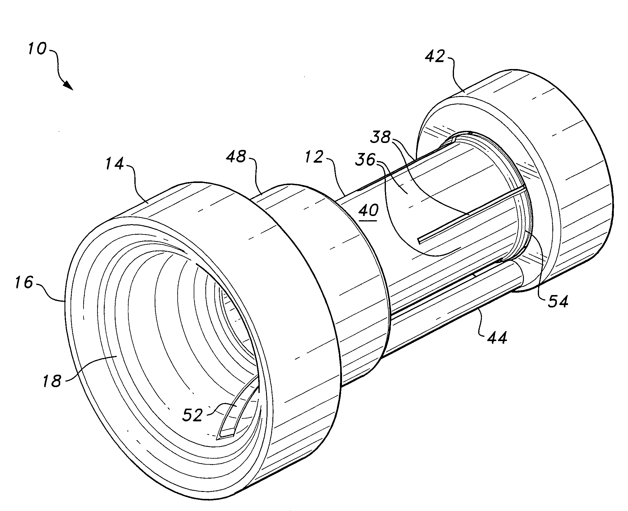
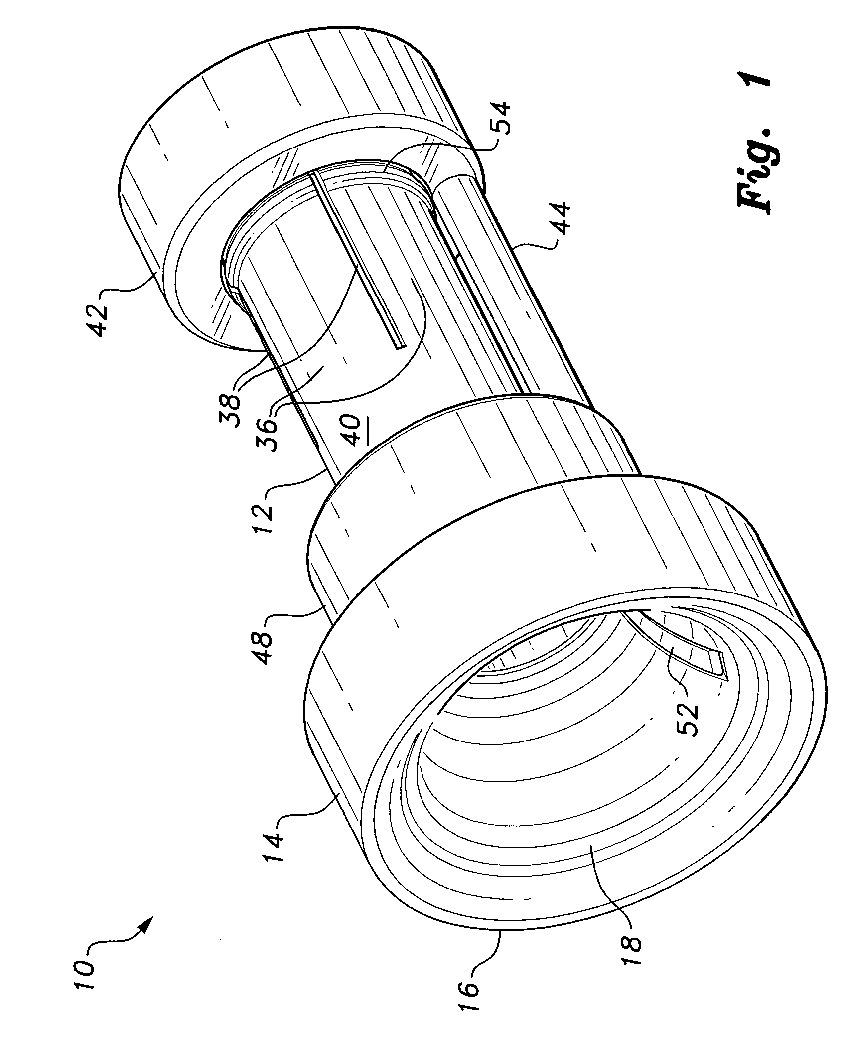
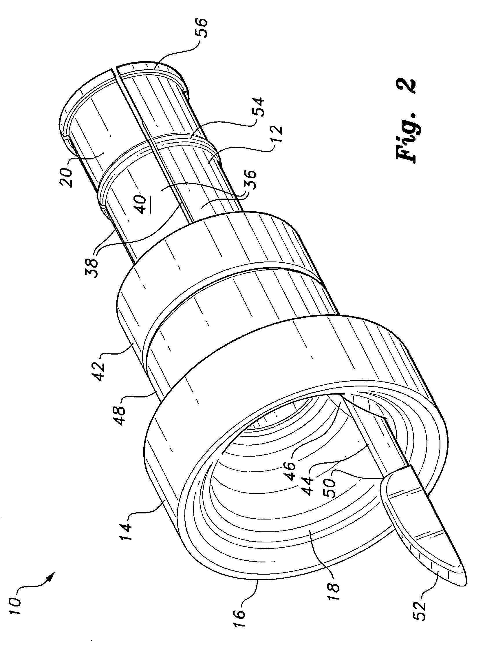
[0029]The stent compression tool works in concert with a diametrically compressible stent and conventional stent delivery catheter to compress and install the stent within the delivery catheter. FIGS. 1 and 2 provide perspective views of the stent compression tool 10 with its second portion retaining collar positioned at the second end of the device, and with the retaining collar moved axially toward the opposite first end, respectively. The tool 10 generally comprises a tube 12 having a relatively large diameter first portion 14 and end 16 with a large funnel opening 18 therein, and an opposite smaller diameter second portion 20 with a relatively smaller diameter opening 22 therein, the smaller diameter opening 22 being concentric with the larger diameter funnel opening 18. These features are shown clearly in FIGS. 4 through 13 of the drawings, which illustrate the sequential steps in the compression of the stent and insertion of the stent into the delivery catheter. The funnel ope...


PUM


Abstract

The stent compression tool is used to install a diametrically compressible stent in a delivery catheter. The tool has a tubular configuration with a larger funnel mouth at one end and a narrower opening at the opposite end. The basic steps in the process comprise extending the stent carrying member from its catheter sheath, passing the carrying member through the tool from the narrower end thereof, placing the stent over the carrying member and compressing the stent by pushing it through the funnel mouth of the tool and the narrower lumen of the tool, inserting the stent grip member of the delivery catheter into the stent and further into the tool, pushing the end of the sheath into the end of the tool, using the carrying member and its stent grip to draw the compressed stent from the tool into the sheath, and removing the tool from the carrying member.

Description

BACKGROUND OF THE INVENTION[0001]1. Field of the Invention[0002]The present invention relates generally to medical devices and equipment, and more particularly to a stent compression tool for diametrically compressing a stent and placing the stent within a stent delivery catheter. A method of stent compression using the tool is also disclosed.[0003]2. Description of the Related Art[0004]The surgical installation of stents, i.e., tubular devices used to repair or maintain an open passage through a bodily vessel, has been known and practiced for a considerable time. Stents are almost universally delivered and installed in the desired location by means of a stent delivery catheter, i.e., a hollow flexible tube or sheath carrying the stent therein. The smallest practicable diameter is most desirable for the delivery catheter, in order to avoid undue trauma to the patient. Yet, the stent itself must be of sufficient diameter to completely fill the diameter of the vessel in which it is in...

Claims


Application Information

Patent Timeline
Patent Type & Authority Applications(United States)
IPC IPC(8): A61F2/06
CPCA61F2002/9522A61F2/95A61F2/9522A61F2/9525
Inventor KUBENA, PETRSEJBL, DOBROMIL
Owner ELLA CS
Why Eureka
Try Eureka