
Control device for an automatic transmission

a control device and automatic transmission technology, applied in the direction of mechanical equipment, digital data processing details, instruments, etc., can solve the problems of not following the actual hydraulic pressure does not follow the desired hydraulic pressure, and the pressure on the forward clutch may not rise as desired, so as to improve the driveability, improve the starting performance of the vehicle, and reduce the viscosity of the hydraulic oil

Inactive Publication Date: 2010-05-13
TOYOTA JIDOSHA KK
View PDF17 Cites 23 Cited by
  • Summary
  • Abstract
  • Description
  • Claims
  • Application Information

AI Technical Summary

Benefits of technology

The present invention provides a control device for an automatic transmission that can prevent slow response of hydraulic pressure and improve smooth engagement of the forward clutch, even at low temperatures. The control device includes a hydraulic oil temperature measuring means, actual speed ratio calculating means, and target speed ratio setting means. The control device can adjust the engaging pressure on the engagement element to a higher value when the hydraulic oil temperature is low, ensuring smooth engagement of the engagement element. This prevents delay in the rise of the engaging pressure and improves the driveability of the vehicle. The control device can also adjust the target speed ratio of the torque converter to a lower value when the hydraulic oil temperature is low, preventing a delay in the engagement of the engagement element. Overall, this control device ensures smooth engagement of the forward clutch and prevents shocks during start-up, improving the performance and driving experience of the vehicle.

Problems solved by technology

However, in the above control device for an automatic transmission, when the temperature of the hydraulic oil for use in engaging the forward clutch is low, the response of hydraulic pressure is slow, in other words, the actual hydraulic pressure does not follow a desired hydraulic pressure, because of the high viscosity of the hydraulic oil, and the engaging pressure on the forward clutch may not rise as desired when the automatic transmission is returned from the neutral mode to the drive mode.
Also, if the engaging pressure on the forward clutch is decreased in view of the fact that the viscosity of the lubricating oil supplied to the frictional engagement element is also high when the temperature is low, the solenoid for controlling the engagement and disengagement of the forward clutch operates in a low pressure range in which the pressure response is slow and the delay in the rise of the engaging pressure on the forward clutch may increase when the automatic transmission is returned from the neutral mode to the drive mode.
As described above, when the temperature of the hydraulic oil is low, the rise in the engaging pressure on the forward clutch delays because of the slow response of the hydraulic pressure or some other reason when the automatic transmission is returned from the neutral mode to the drive mode.
Thus, the forward clutch cannot be engaged smoothly when the vehicle is started.
As a result, a shock occurs to the vehicle or the starting performance of the vehicle is deteriorated, resulting in poor driveability.

Method used


Image

  • Control device for an automatic transmission
  • Control device for an automatic transmission
  • Control device for an automatic transmission

Examples


Embodiment Construction

[0030]Description is hereinafter made of an embodiment of the present invention with reference to the drawings.

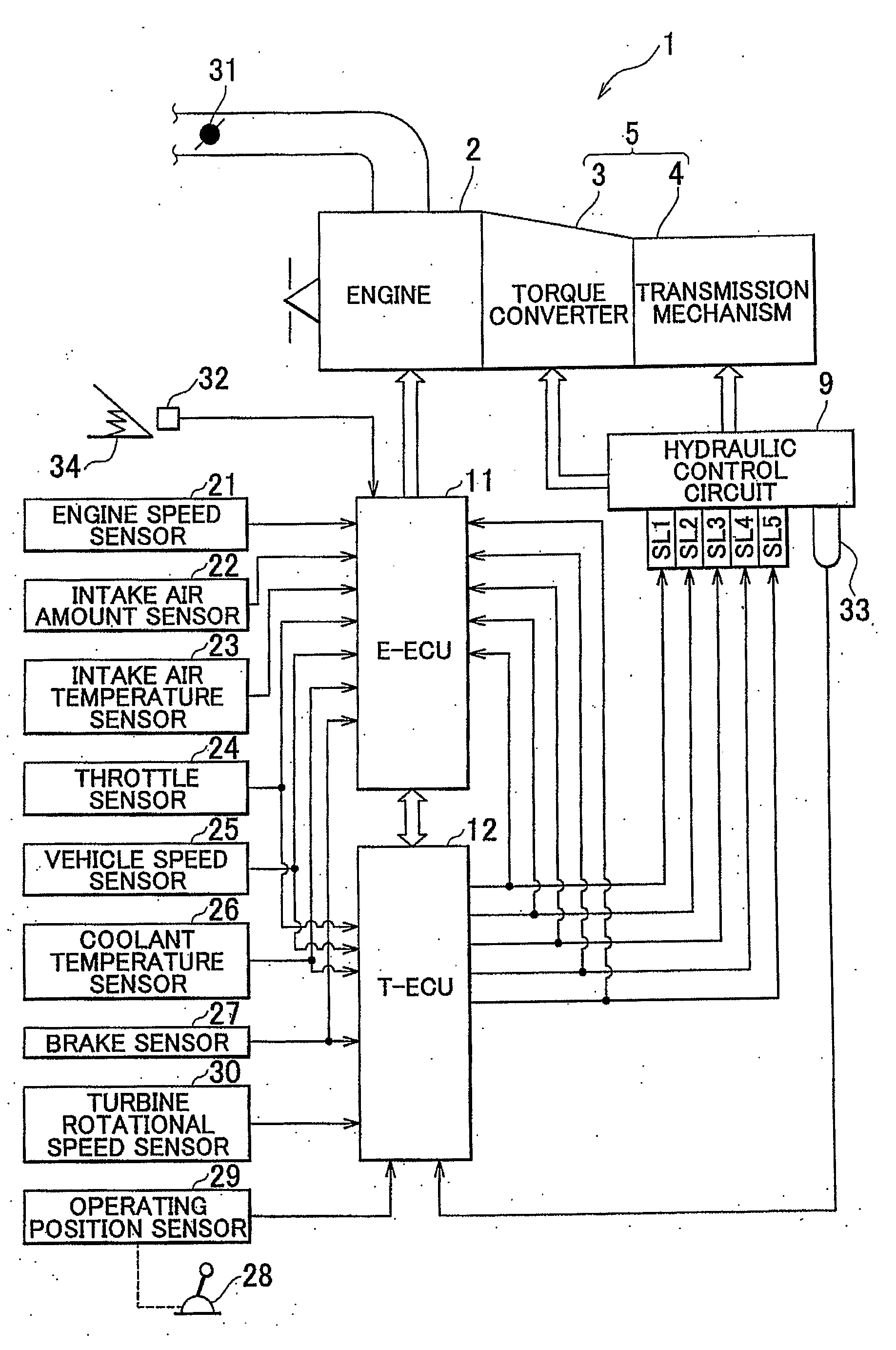
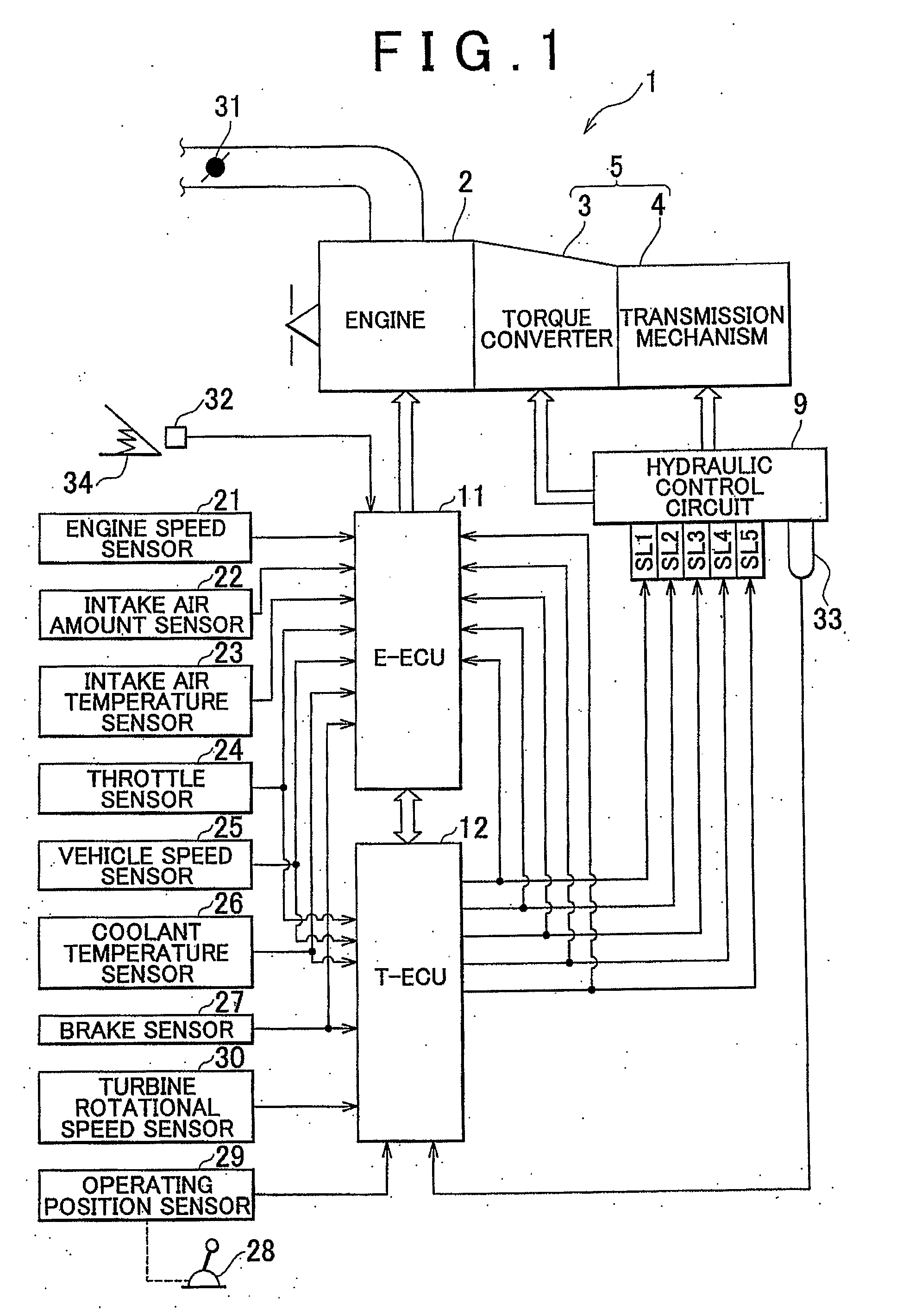
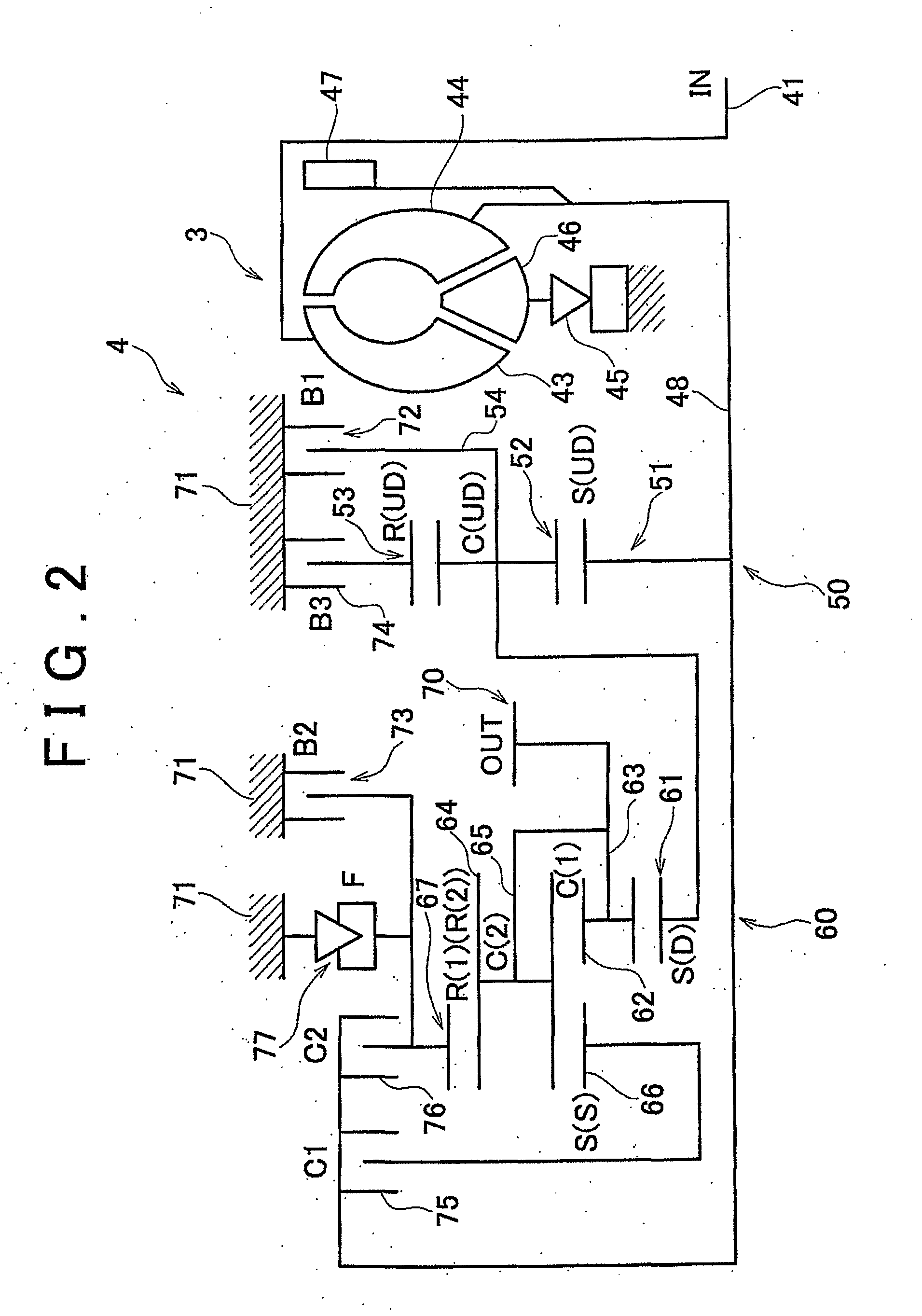
[0031]FIG. 1 is a general configuration diagram schematically illustrating a vehicle provided with a control device for an automatic transmission according to one embodiment of the present invention. FIG. 2 is an outline diagram illustrating the configuration of the control device for an automatic transmission according to the embodiment of the present invention.

[0032]In this embodiment, the case where the control device for an automatic transmission according to the present invention is applied to an FF (Front engine Front drive) vehicle is described.

[0033]As shown in FIG. 1, a vehicle 1 has an engine 2; a torque converter 3; a transmission mechanism 4 having a forward clutch; a hydraulic control circuit 9 for controlling the torque converter 3 and the transmission mechanism 4 by hydraulic pressure; an engine ECU (Electronic Control Unit) 11 for controlling the engine 2 as...


PUM


Abstract

A transmission ECU 12 determines whether or not the conditions for executing a neutral control operation are satisfied (step S11), and measures hydraulic oil temperature if it determines that the execution conditions are satisfied (step S12). Then, the transmission ECU 12 sets a target speed ratio for a torque converter 3 corresponding to the measured hydraulic oil temperature (step S13), and performs a neutral control operation to bring the speed ratio of the torque converter 3 equal to the target speed ratio (step S14).

Description

BACKGROUND OF THE INVENTION[0001]1. Field of the Invention[0002]The present invention relates to a control device for an automatic transmission, and, in particular, to a control device for an automatic transmission which performs a neutral control operation.[0003]2. Description of the Related Art[0004]In general, in a control device for an automatic transmission, when the vehicle is stopped in a forward range, a creep phenomenon occurs in which the driving force generated by the idling rotation of the engine is transmitted as creep force to the driving wheels via torque converter and transmission mechanism. To keep the vehicle stationary, the driver must operate the brake to suppress the creep force, and the fuel efficiency of the engine decreases by the amount corresponding to the creep force consumed by the brake. Thus, when vehicle is stationary in a forward range with the brake pedal depressed to actuate the brake and accelerator almost fully closed, the control device for an au...

Claims


Application Information

Patent Timeline
Patent Type & Authority Applications(United States)
IPC IPC(8): G06F19/00F16H59/42F16H59/46F16H59/56F16H59/72F16H59/74F16H61/20F16H61/68F16H61/684F16H61/686
CPCF16H59/72F16H61/20F16H2312/022Y10T477/635Y10T477/73Y10T477/633F16H2061/207
Inventor TSUKAMOTO, NORIHIROAYABE, ATSUSHI
Owner TOYOTA JIDOSHA KK
Learn More