Driving device for an electric lock latch

Inactive Publication Date: 2010-05-20
LUI PANG CHENG
View PDF17 Cites 36 Cited by
  • Summary
  • Abstract
  • Description
  • Claims
  • Application Information

AI Technical Summary

Benefits of technology

[0007]An object of the invention is to eliminate the above-mentioned drawbacks of the conventional equidimensional spring activated by a pin and to provide a driving device for an electric lock latch wherein the middle part of the spiral spring is constructed as the threaded joint portion having a smaller diameter in threaded connection to the threaded portion of the d

Problems solved by technology

However, the activation of the electromagnetic valve requires a large power consumption.
As a result, the installer must have the electronic knowledge and the installation s

Method used


Image

  • Driving device for an electric lock latch
  • Driving device for an electric lock latch
  • Driving device for an electric lock latch

Examples


first embodiment

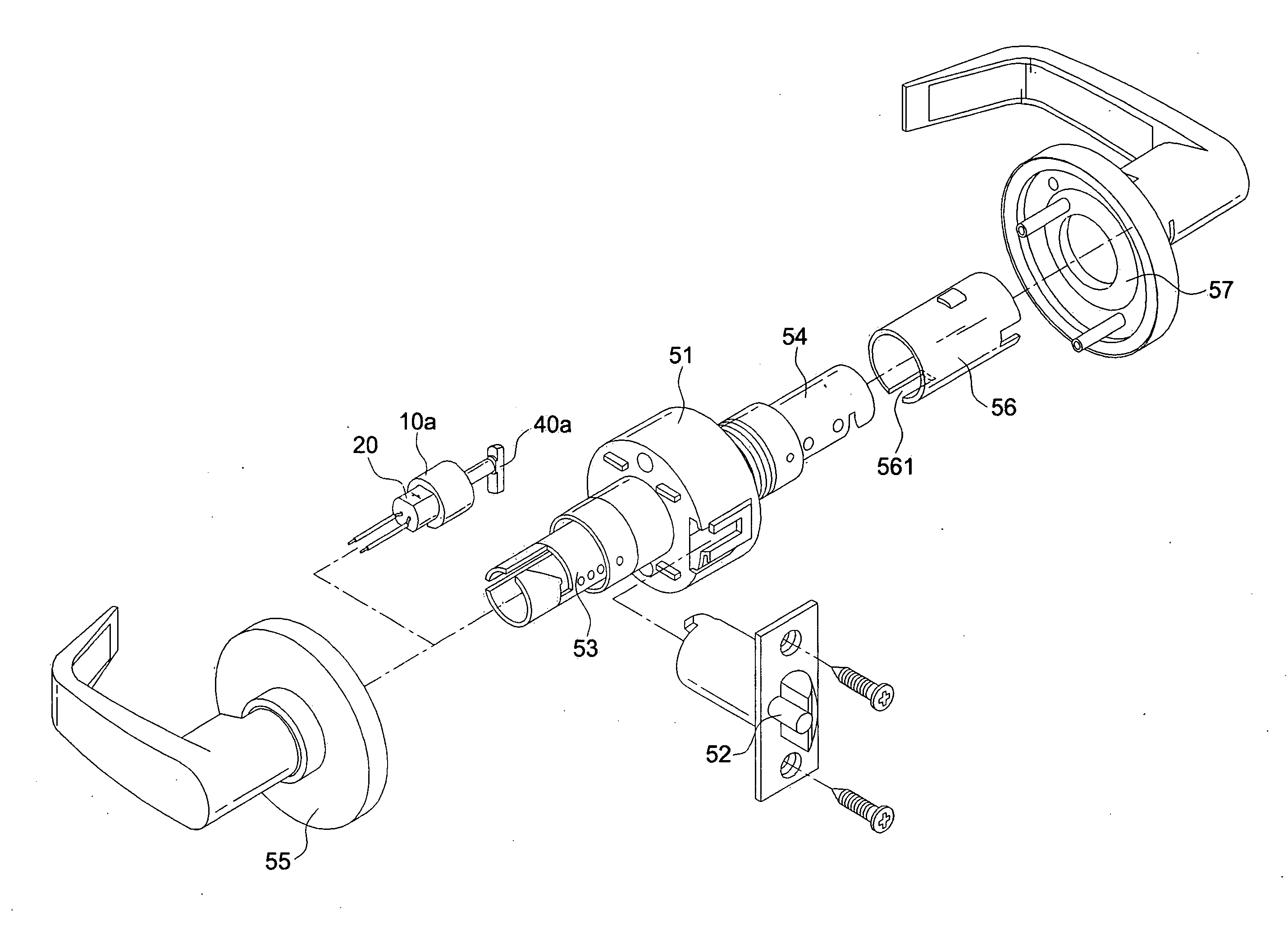
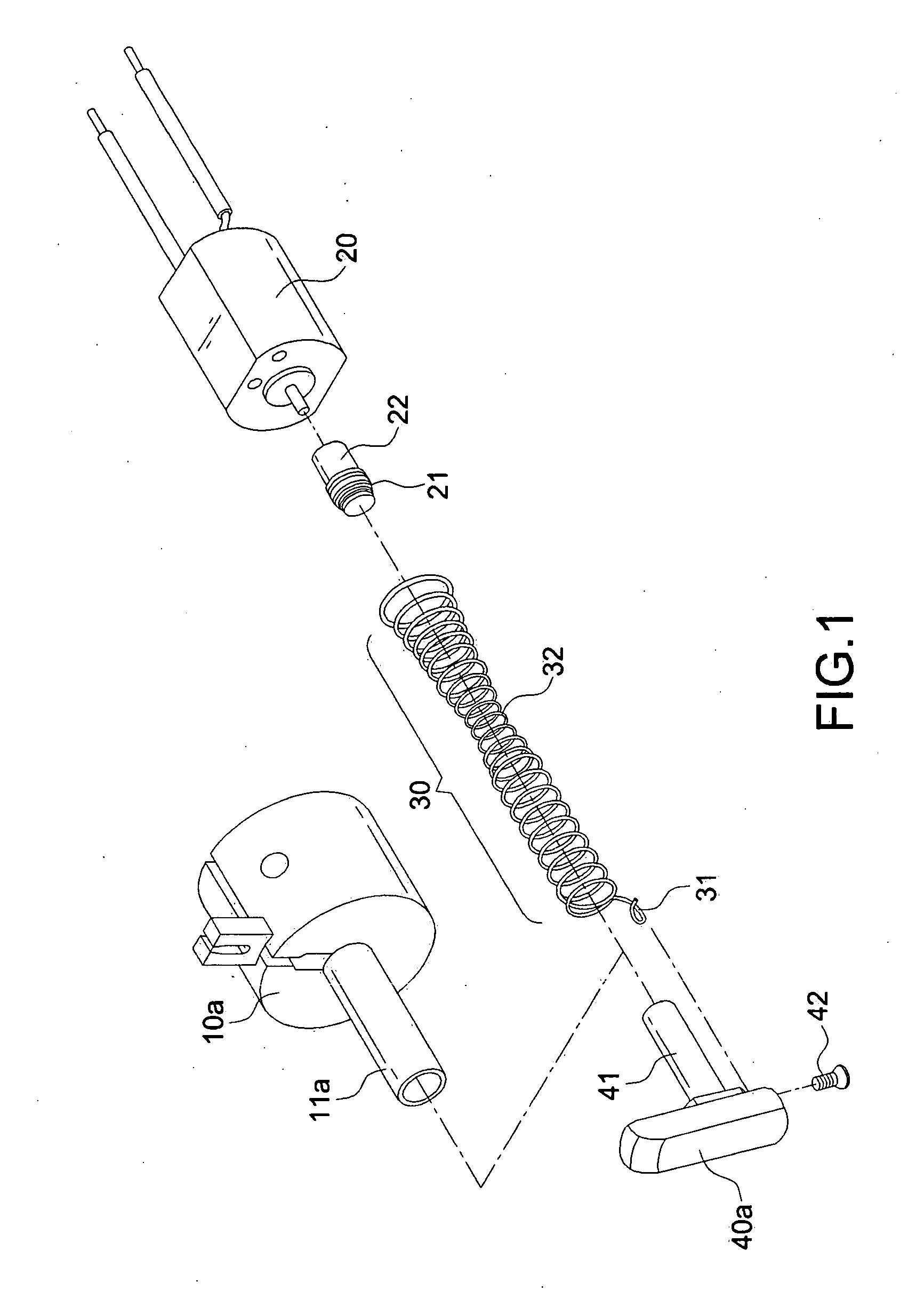
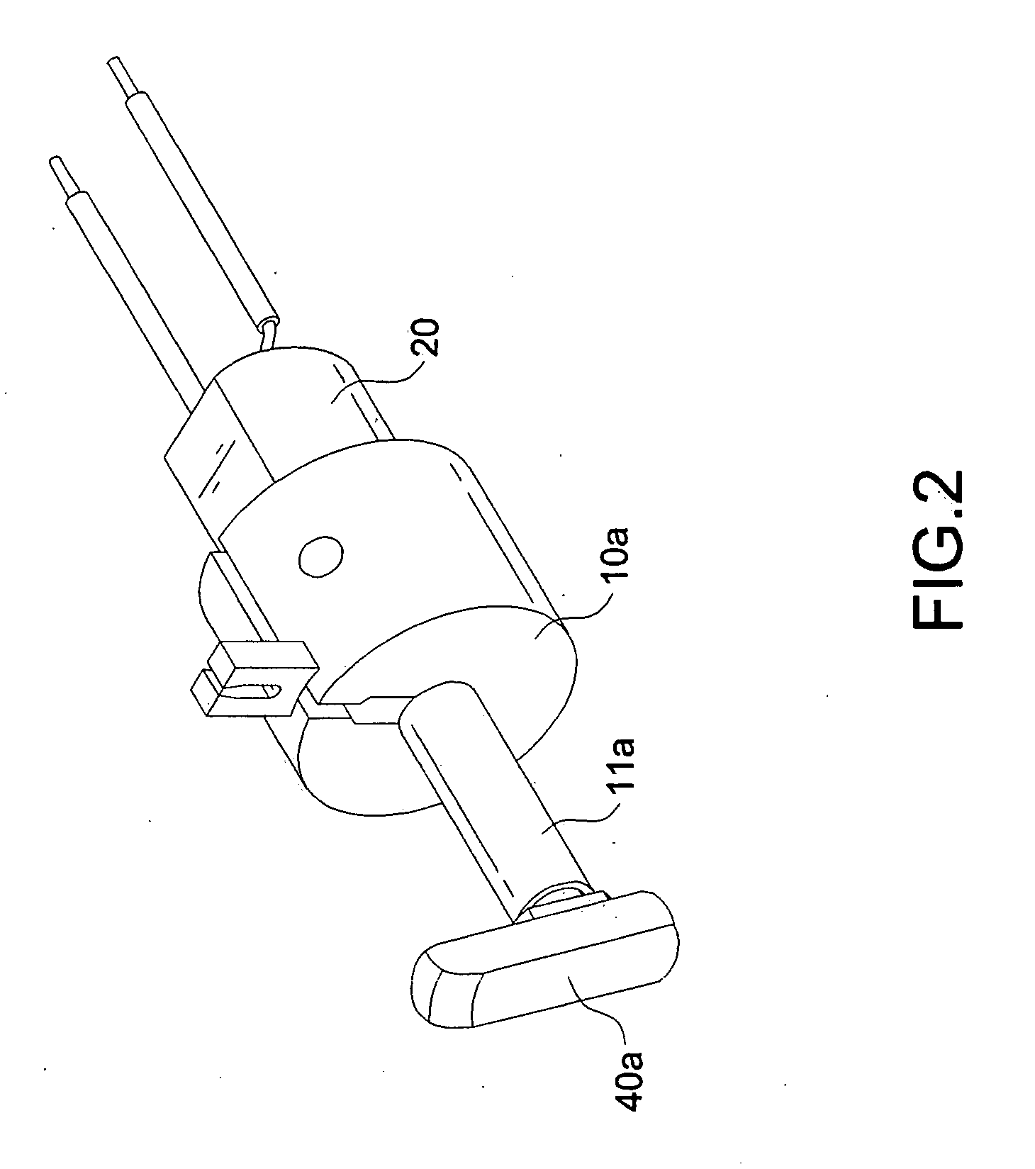
[0026]First of all, referring to FIGS. 1 and 2, the structure in accordance with the invention includes a housing 10a, a motor 20, a spiral spring 30, and a lock latch 40a.

[0027]The motor 20 is positioned within the housing 10a with a power output shaft secured to a drive shaft 22 with a threaded portion 21.

[0028]The spiral spring 30 includes an internal part fixed in the housing 10a or at the motor 20. The middle part of the spiral spring 30 includes a threaded joint portion 32 (with a smaller diameter) corresponding to the threaded portion 21 of the drive shaft 22. The internal and external parts of the spiral spring 30 do not have the threaded connection to the threaded portion 21 of the drive shaft 22. The housing 10a further includes a guide slot 11a corresponding to the spiral spring 30.

[0029]The lock latch 40a is secured to the external part of the spiral spring 30. The lock latch 40a includes an insertion portion 41 fitting into the external part of the spiral spring 30, th...

second embodiment

[0032]Referring to FIGS. 7 and 8, the structure in accordance with the invention includes a housing 10b, a motor 20, a spiral spring 30, and a lock latch 40b.

[0033]The motor 20 is positioned within the housing 10b with a power output shaft secured to a drive shaft 22 with a threaded portion 21.

[0034]The spiral spring 30 includes an internal part fixed in the housing 10a or at the motor 20. The middle part of the spiral spring 30 includes a threaded joint portion 32 (with a smaller diameter) corresponding to the threaded portion 21 of the drive shaft 22. The internal and external parts of the spiral spring 30 do not have the threaded connection to the threaded portion 21 of the drive shaft 22. The housing 10b further includes a guide slot 11b corresponding to the spiral spring 30.

[0035]The lock latch 40b is secured to the external part of the spiral spring 30. The lock latch 40b includes an mounting sleeve 43 fitting over the external part of the spiral spring 30, thereby creating a...


PUM


Abstract

A driving device for an electric lock latch, comprising: a) a housing; b) a motor positioned within the housing with a power output shaft secured to a drive shaft with a threaded portion; c) a spiral spring having an internal part fixed in the housing or at the motor, the middle part of the spiral spring having a threaded joint portion (with a smaller diameter) corresponding to the threaded portion of the drive shaft, the internal and external parts of the spiral spring not having the threaded connection to the threaded portion of the drive shaft; and d) a lock latch secured to the external part of the spiral spring. Unlike the conventional structure requiring an external power source, thereby leading to a complicated installation, the structure in accordance with the invention includes a drive shaft having a threaded portion for driving a spiral spring in threaded connection thereto. Moreover, the lock latch is connected at the external part of the spiral spring. As a result, the circular motion of the drive shaft is converted into the rectilinear motion of the spiral spring such that the lock latch is moved. In this way, the locked and unlocked state of the lock device may be changed by the movement of the lock latch. Accordingly, the lock structure and the installation thereof may be simplified. Meanwhile, the power-saving effect is achieved.

Description

BACKGROUND OF THE INVENTION[0001]1. Field of the Invention[0002]The invention relates to a driving device for an electric lock latch, and more particularly to a structure with a drive shaft having a threaded portion for driving a spiral spring in threaded connection thereto. Moreover, the lock latch is connected at the external part of the spiral spring. As a result, the circular motion of the drive shaft is converted into the rectilinear motion of the spiral spring such that the lock latch is moved. In this way, the locked and unlocked state of the lock device may be changed by the movement of the lock latch. Moreover, the structure of the invention can be applied to all kinds of lock devices.[0003]2. Description of the Related Art[0004]It is quite normal that the lock employs an electromagnetic valve to control the movement of the latch, thereby changing the locked or unlocked state. Such a structure is disclosed in the U.S. Pat. No. 6,082,791. However, the activation of the elect...

Claims


Application Information

Patent Timeline
IPC IPC(8): E05B47/00
CPCE05B47/0012E05B47/0673E05B47/068E05B2047/0023E05B2015/0496E05B2047/0016E05B2015/0406Y10T70/7062
Inventor LUI, PANG-CHENG
Owner LUI PANG CHENG
Why Eureka
Try Eureka