
Engine Tool

Inactive Publication Date: 2010-05-20
HITACHI KOKI CO LTD
View PDF10 Cites 10 Cited by
  • Summary
  • Abstract
  • Description
  • Claims
  • Application Information

AI Technical Summary

Benefits of technology

[0017]According to the engine tool of the present invention, heat from the engine is not likely to be transmitted to a user, so that the user can work comfortably.

Problems solved by technology

Accordingly, the plastic-made housing has inferior rigidity of a material itself and the strength thereof in comparison with a metallic housing, and the heat dissipation characteristics are also poor.

Method used


Image

  • Engine Tool
  • Engine Tool
  • Engine Tool

Examples


Embodiment Construction

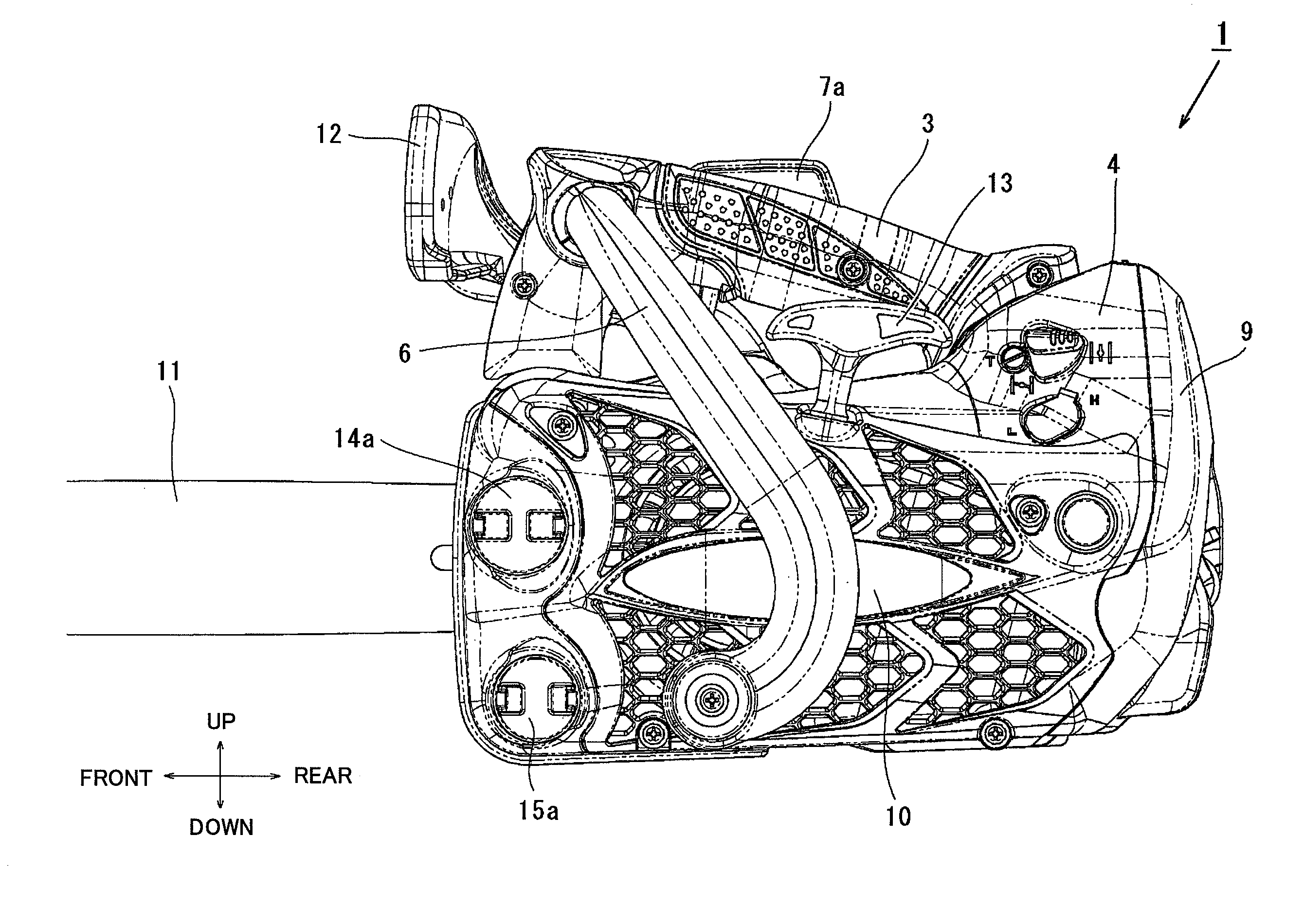
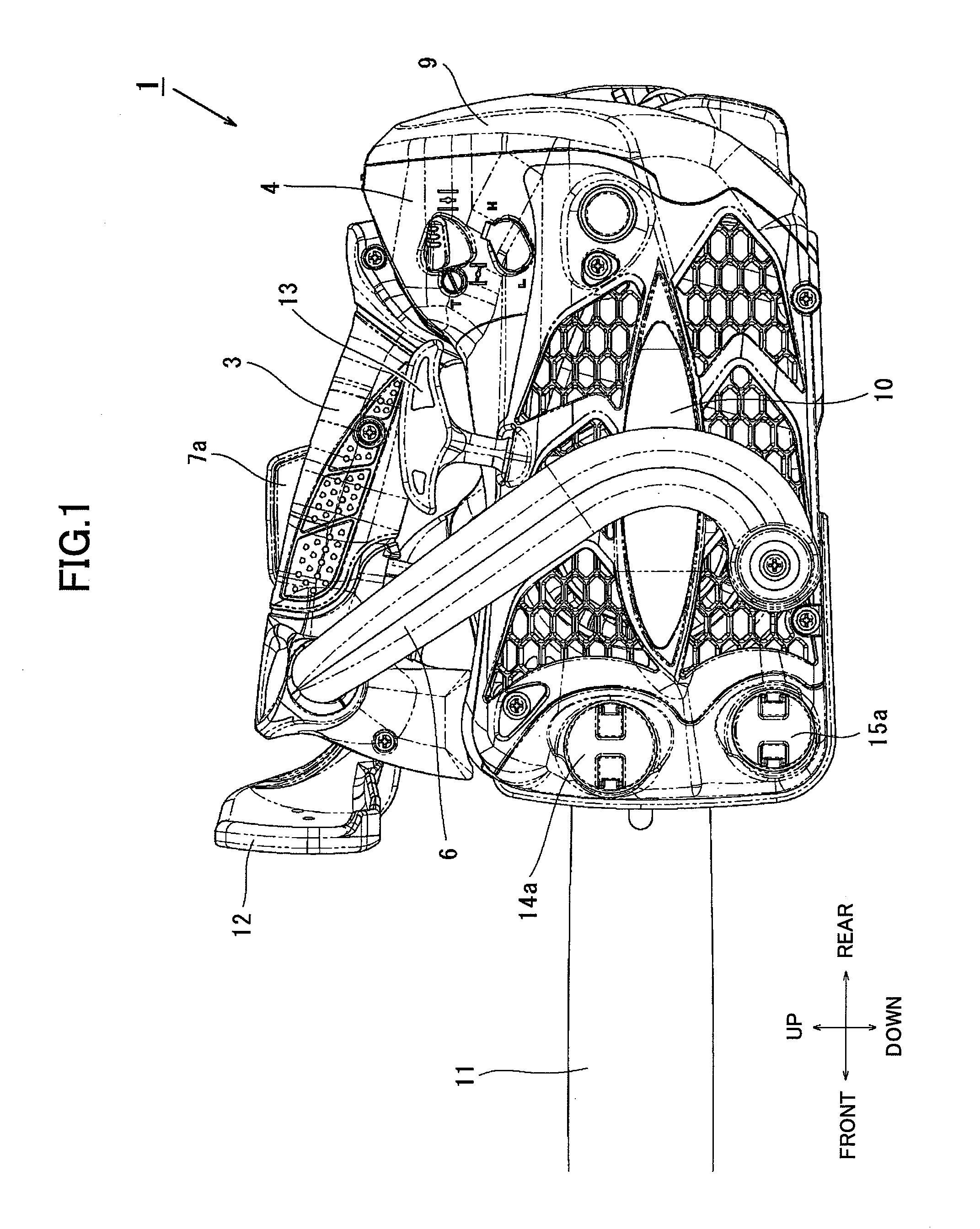
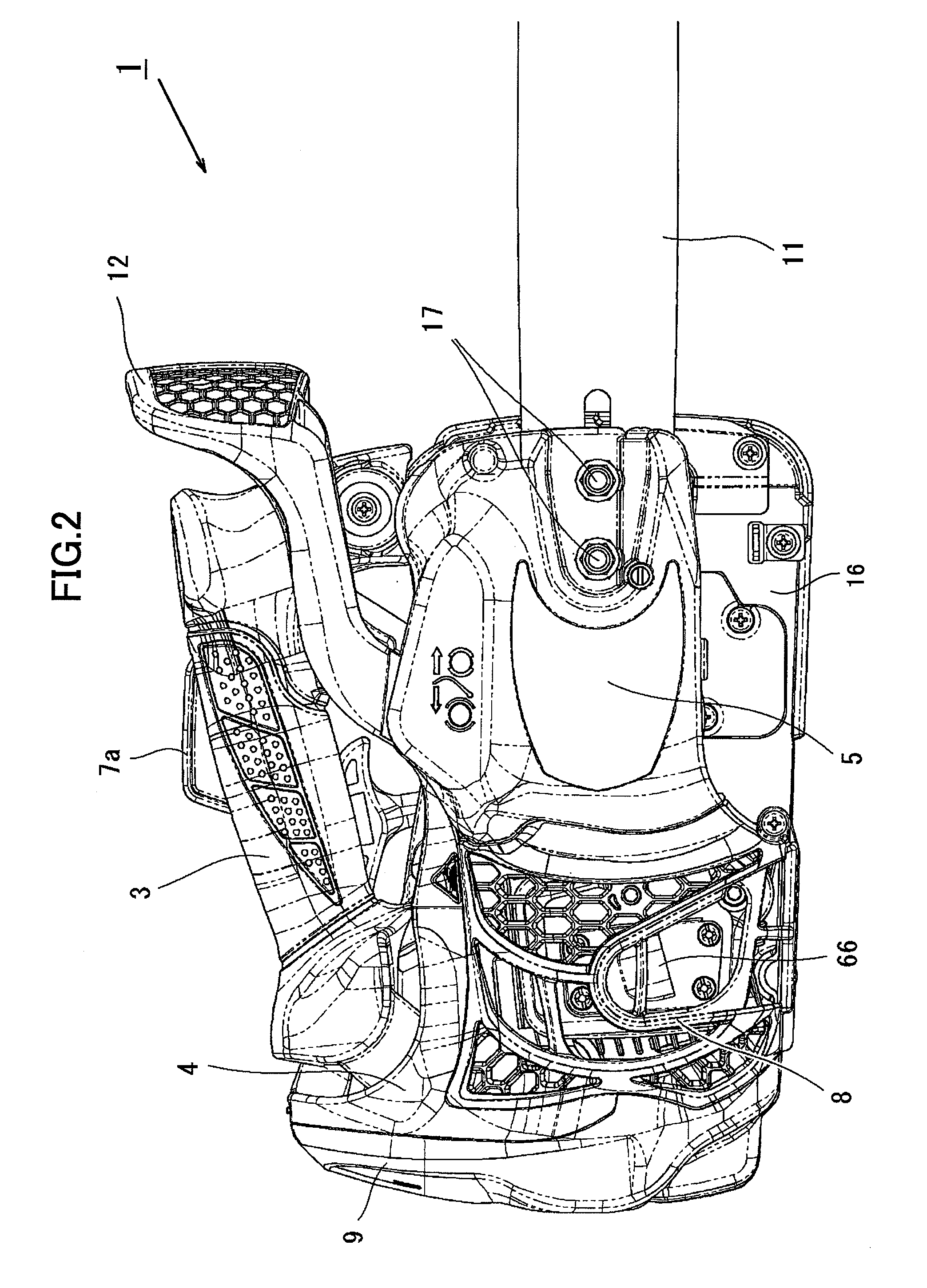
[0031]An explanation will be given of an embodiment of the present invention with reference to accompanying drawings. The explanation will be given of a chainsaw as an example of an engine tool, the same structural elements will be denoted by the same reference numerals across the accompanying drawings, and the repeated explanation will be omitted. FIG. 1 is a left side view of a chainsaw of the embodiment, FIG. 2 is a right side view, and FIG. 3 is a back view.

[0032]As shown in FIG. 1, a chainsaw 1 has a small engine, such as a two-cycle engine or a four-cycle engine, as a power source. In the specification, backward and forward and vertical directions are defined as shown in FIG. 1 with a user being holding the chainsaw 1, and leftward and rightward directions are defined as shown in FIG. 3. A guide bar 11 protrudes from the front part of a main body of the chainsaw 1. A saw chain (not shown) is wound around the circumferential edge of the guide bar 11. The saw chain is rotated at...


PUM


Abstract

An engine tool comprises an engine, a housing retaining the engine, a top cover provided above the housing, and an air cleaner room provided at the housing. The engine tool is structured in such a way that external air introduced in the air cleaner room or the housing flows through a space formed between the housing and the top cover. The engine tool further comprises a handle part which is grabbed by a user and which is provided above the top cover. External air flows through a space formed between an area of the top cover where the handle part is provided and the housing. The engine tool still further comprises an air inlet for introducing external air provided at a front part of the engine tool.

Description

CROSS-REFERENCES TO RELATED APPLICATIONS[0001]This application is based on Japanese Patent Application No. 2008-291833 filed on Nov. 14, 2008 and including specification, claims, drawings and summary. The disclosure of the above Japanese Patent Application is incorporated herein by reference in its entirety.BACKGROUND OF THE INVENTION[0002]1. Field of the Invention[0003]The present invention relates to an engine tool with a small engine like a chainsaw, and more particularly, an engine tool having a devised air cleaner room or airflow path for engine cooling.[0004]2. Description of the Related Art[0005]Engine tools like chainsaws for cutting a shaft of a tree or a branch thereof are generally driven by a small engine. In general, because a user cuts a branch above his / her head or climbs the tree while holding the chainsaw, the chainsaw is small and light-weighted so that the user can easily lift up the chainsaw by one hand. The chainsaw also has a handle so that the user can easily ...

Claims


Application Information

Patent Timeline
IPC IPC(8): F02B77/00F02M35/02
CPCB25F5/008B27B17/08F02B63/02H01L2924/0002H01L2924/00
Inventor KAWANA, KAZUYUKIODA, KOUHEI
Owner HITACHI KOKI CO LTD
Learn More