Static thermal-storage heating-amount slow-release structure and construction process and use thereof

A construction technique and heat storage technology, which is applied in the field of geothermal electric heating static heat storage heating heat slow release structure, can solve the problems of adverse environmental impact, low efficiency of comprehensive energy utilization, water heat storage technology is not suitable for urban heating, etc. It achieves the effects of saving investment and operating costs, being easy to adjust and control intelligently, and improving the quality of the atmospheric environment

Inactive Publication Date: 2004-04-14
孙侠
View PDF0 Cites 10 Cited by
  • Summary
  • Abstract
  • Description
  • Claims
  • Application Information

AI Technical Summary

Problems solved by technology

[0003] 1. Most of them use electric radiators, electric heaters, and electric water heaters for direct heating, and the comprehensive energy utilization efficiency is low, only 30%. In addition, warm air is used for heating. When the distance is long, cold wind is formed due to heat dissipation and air exchange, and the comfort of indoor personnel is poor (factors that affect comfort include temperature, air pressure, humidity, wind speed, etc.);
[0004] 2. The electric heating film ceiling radiation heating with low cost but relatively simple technology has poor comfort and safety, and the surface temperature of the radiator exceeds the national standard;
[0005] 3. Household central air-conditioning technology of air heat pump, the heating capacity is limited by temperature, which has adverse effects on the environment;
[0006] 4. Groundwater electric heat pump heating, which uses low-temperature heat exchange technology to pump out groundwater and use its heat energy. Although the conversi

Method used


Image

  • Static thermal-storage heating-amount slow-release structure and construction process and use thereof
  • Static thermal-storage heating-amount slow-release structure and construction process and use thereof
  • Static thermal-storage heating-amount slow-release structure and construction process and use thereof

Examples


Example Embodiment

[0033] Example 1

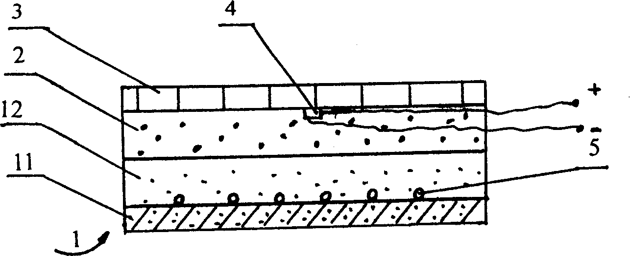
[0034] Such as figure 1 As shown, the floor structure diagram of the floor slab heating by using the geothermal cable of the present invention is a laminated structure of a thermal storage layer 1 and a slow-release layer 2. The thermal storage layer 1 is a two-layer, including a direct thermal storage layer 12 and an indirect thermal storage layer 12 The thermal storage layer 11 is arranged in order from top to bottom, the geothermal cable 5 is embedded in the direct thermal storage layer 1, the slow release layer 2 is covered with a decorative layer 3, and the temperature sensor 4 is connected in series with the geothermal cable 5 loop It is arranged at the bottom of the decoration layer 3 and is in contact and connection with the decoration layer 3. The indirect heat storage layer 11 is a floor slab, and the direct heat storage layer 12 uses cement mortar, and its thermal conductivity is 0.4w·m -1 ·K -1 , The weight ratio of cement and sand is 1:3; the slow-...


PUM

PropertyMeasurementUnit
Thermal conductivityaaaaaaaaaa

Abstract

The present invention relates to a geothermic electric heating static heat-stored heating heat quantity slowly-releasing structure, its construction process and application. Its structure comprises up-down laminated heat-storing layer and heat quantity slowly-releasing layer, the geothermic cable is embedded in the heat-storing layer formed from heat-storing material whose heat-conducting coefficient is 0.3-0.79w.m(-1).k(-1), said heat-storing layer is covered with the slowly-releasing layer formed from slowly-releasing material whose heat-conducting coefficient is 0.04-0.07 w.m(-1).k(-1), and the temp. sensor is embedded in the slowly-releasing layer, and is series-connected with geothermal cable loop. Its application includes the following steps: starting power supply to supply power to geothermic cable, and storing heat energy in heat-storing layer, then slowly-releasing the heat energy to heating space by means of slowly-releasing layer.

Description

Technical field [0001] The invention relates to electric heating technology, in particular to a geothermal electric heating static heat storage type heating heat slow release structure and its construction technology and application. Background technique [0002] The existing electric heating technology still has some imperfect aspects: [0003] 1. Most of them use electric radiators, electric heaters, and electric water heaters for direct heating. The comprehensive energy utilization efficiency is low, only 30%; in addition, warm air is used for heating. When blowing at close distances, people will be suffocated due to too much heat. When the distance is far away, it will become cold due to heat dissipation and air exchange, and the comfort of indoor personnel is poor (factors affecting comfort are temperature, air pressure, humidity, wind speed, etc.); [0004] 2. The low-cost but simpler technology of electric heating film ceiling radiant heating is poor in comfort and safety,...

Claims


Application Information

Patent Timeline
IPC IPC(8): F24D13/02F24D19/10
CPCY02B10/40
Inventor 孙侠宋勤
Owner 孙侠
Why Eureka
Try Eureka