Air cap with air director

Inactive Publication Date: 2010-05-20
J WAGNER GMBH
View PDF14 Cites 8 Cited by
  • Summary
  • Abstract
  • Description
  • Claims
  • Application Information

AI Technical Summary

Benefits of technology

[0038]Forming an air director and/or an air cap by the injection molding method has the advanta

Problems solved by technology

To produce an air cap materially in one piece with air directors, complicated and cost-intensive injection molds are required in order to fulfill the usually stringent requirements with regard to form geometry or surface quality of such components.
Furthermore, the freedom of configuration, especially in the r

Method used


Image

  • Air cap with air director
  • Air cap with air director
  • Air cap with air director

Examples


Embodiment Construction

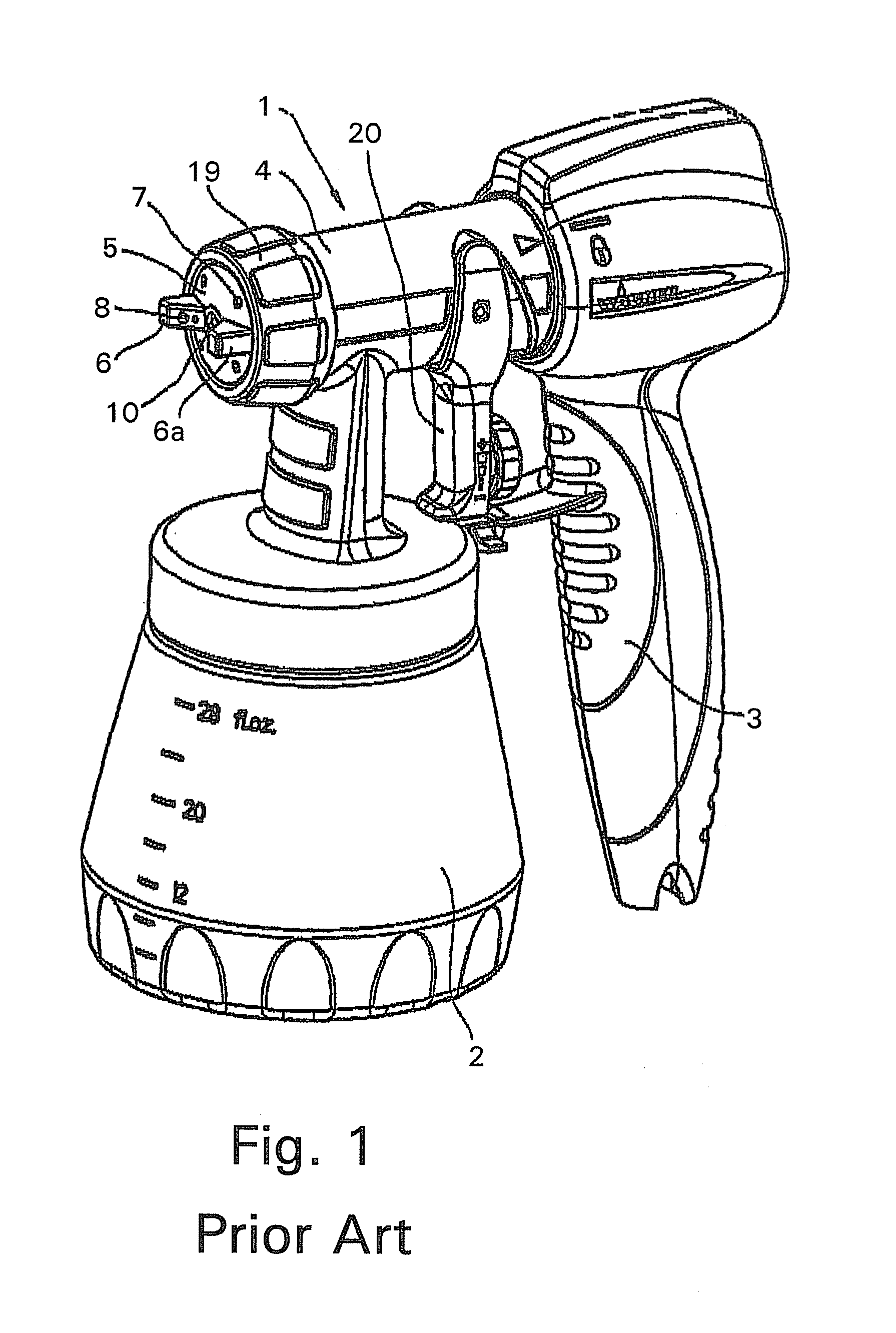
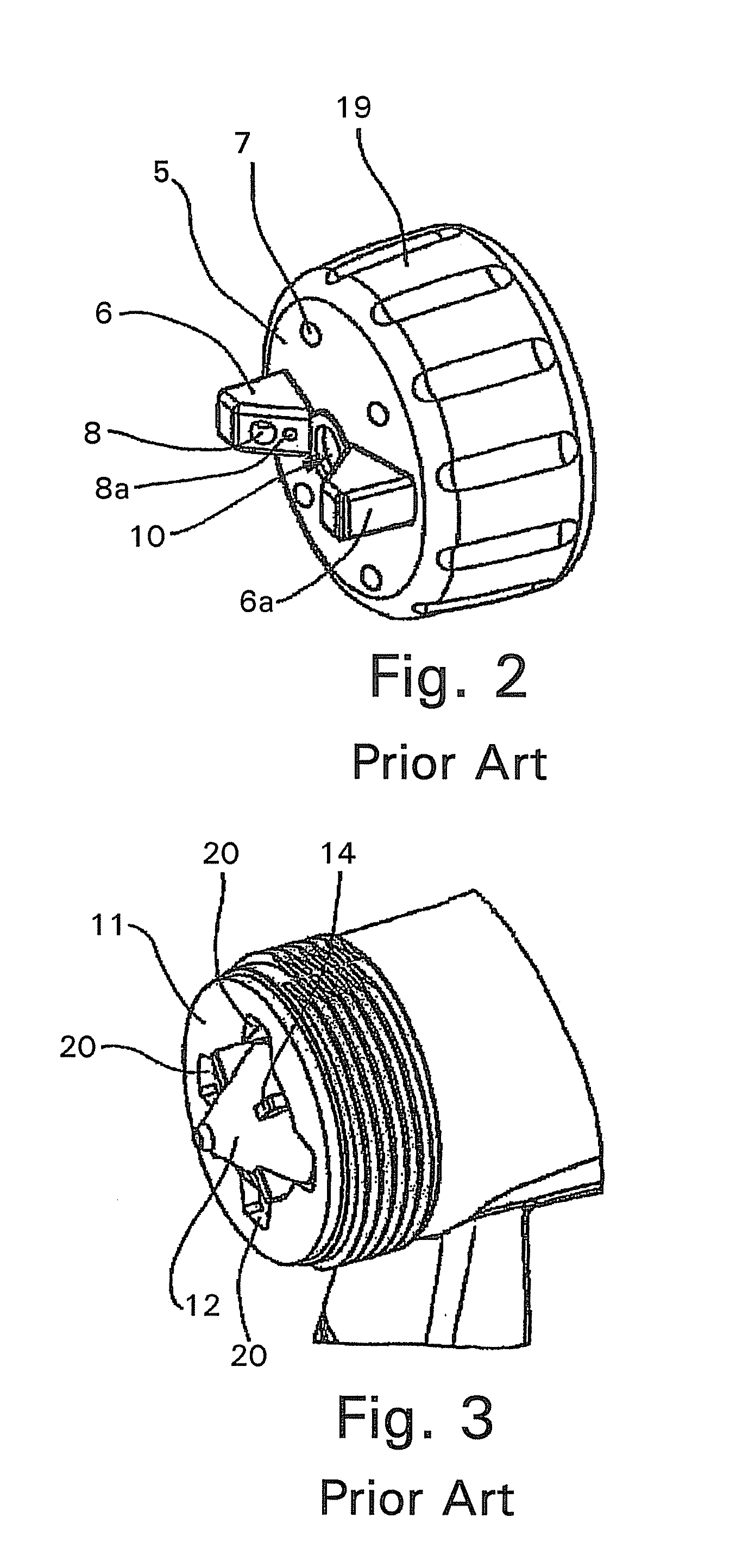
[0046]FIG. 1 shows a conventional spray gun 1 for liquids, preferably for paints, which has a liquid container 2, a handle element 3 and, at the front end of a gun housing 4, an air cap 5 with air directors 6, 6a arranged in one piece on the latter, the air cap 5 being held on the gun housing 4 by means of a union nut 19.

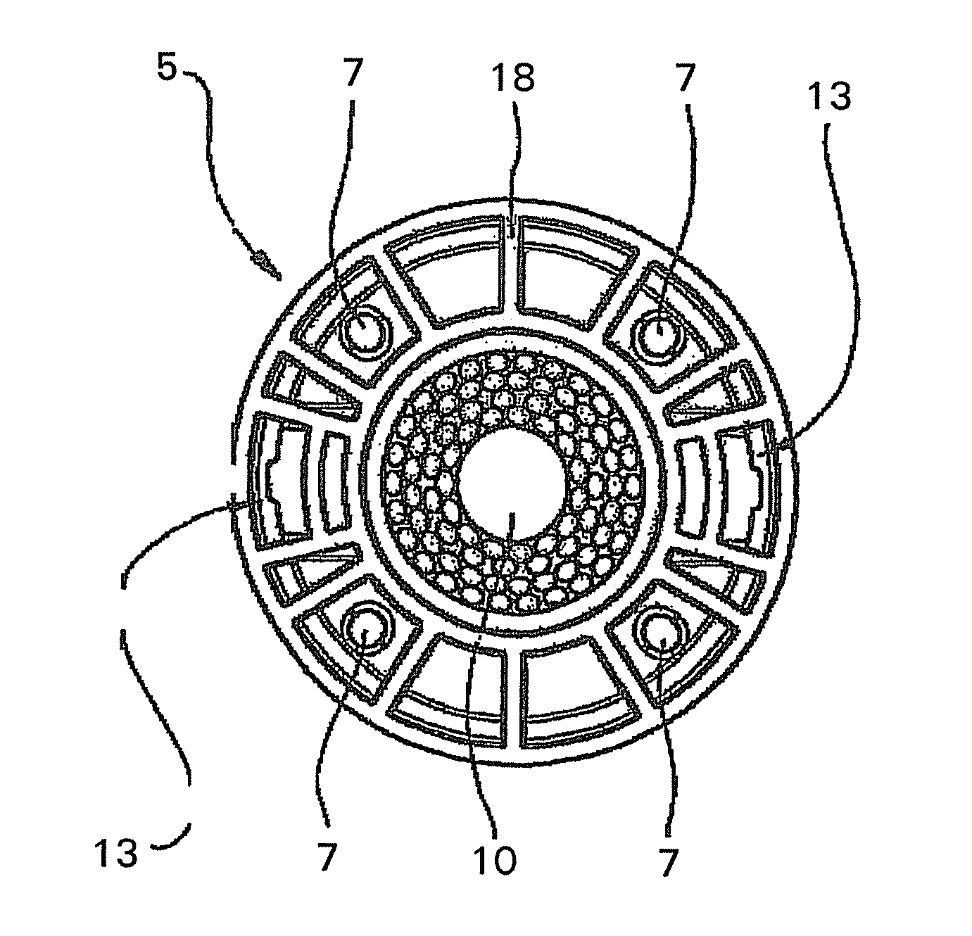
[0047]When the spray gun 1 is in operation, a liquid paint emerges from a paint nozzle 12 (illustrated in FIG. 3) as a result of the actuation of a pull lever 20 and is atomized in the region of a central recess 10 of the air cap 5 by means of outflowing air, the air being supplied continuously to the spray gun 1.

[0048]An atomized paint jet has preferentially a circular surface geometry when no air directors 6 are present.

[0049]The air cap 5 is designed, on its outwardly directed surface, with two air directors 6, 6a which are arranged diametrically opposite one another and are connected in one piece to the air cap and through each of which an air duct 8 passes.

[005...


PUM

PropertyMeasurementUnit
Surface roughnessaaaaaaaaaa

Abstract

An air cap for generating an air stream by means of an atomized liquid is proposed, the liquid being atomized via a liquid nozzle, preferably with a needle valve, in the region of an air outlet orifice of the air cap, and the air cap comprising at least one further air outlet orifice which is connected to at least one following air director and which generates a directed air jet. According to the invention, the air director is produced, in particular formed, as a separate element and is connectable to the air cap.

Description

[0001]This application claims the benefit under 35 USC §119(a)-(d) of European Application No. 08 020 164.3 filed Nov. 19, 2008, the entirety of which is incorporated herein by reference.FIELD OF THE INVENTION[0002]The invention relates to an air cap for generating an air stream by means of an atomized liquid.BACKGROUND OF THE INVENTION[0003]Liquids, especially paints for the coating and protection of surfaces, are applied to a surface in a known way by means of spray guns. Such spray guns for atomizing a liquid paint are known in a multiplicity of different embodiments.[0004]For an effective homogeneous application of paint to a surface, an important criterion for use is in this case the exploitable range of paint jet geometry. A preferred paint jet geometry for surface treatment is, for example, a flat jet form.[0005]The publication EP 1 880 771 A1 shows a spray gun for the spraying of paints, a union nut arranging an air cap, having two air directors (air horns) arranged diametri...

Claims


Application Information

Patent Timeline
IPC IPC(8): B05B1/28B23P17/04B29C45/00
CPCY10T29/49826B05B7/0815
Inventor GOHRING, ALFREDIBELE, PETERPROBST, HERMANN
Owner J WAGNER GMBH
Why Eureka
Try Eureka