Wave energy converter

a converter and wave energy technology, applied in the direction of mechanical equipment, machines/engines, electric generator control, etc., can solve the problems of complex wec to respond to transient waves, the apparatus of the wec must change a mass, and many wecs are not equipped to respond to wave changes

Inactive Publication Date: 2010-05-20
HOBDY MILES
View PDF6 Cites 61 Cited by
  • Summary
  • Abstract
  • Description
  • Claims
  • Application Information

AI Technical Summary

Problems solved by technology

One problem associated with WECs is that to adapt to the transient nature of waves, the apparatus of the WEC must change a mass, stiffness or damping characteristic.
Many WECs are not equipped to respond to the changes in waves.
The ability of a WEC to respond to transient waves requires additional components and complexity, which further compounds the potential maintenance and reliability issues of a WEC.
Another problem associated with current WECs is that the parts that convert wave energy to electrical energy are exposed directly to the environment.
Therefore, these parts are subject to corrosion and disrepair.

Method used


Image

  • Wave energy converter
  • Wave energy converter
  • Wave energy converter

Examples


fifth embodiment

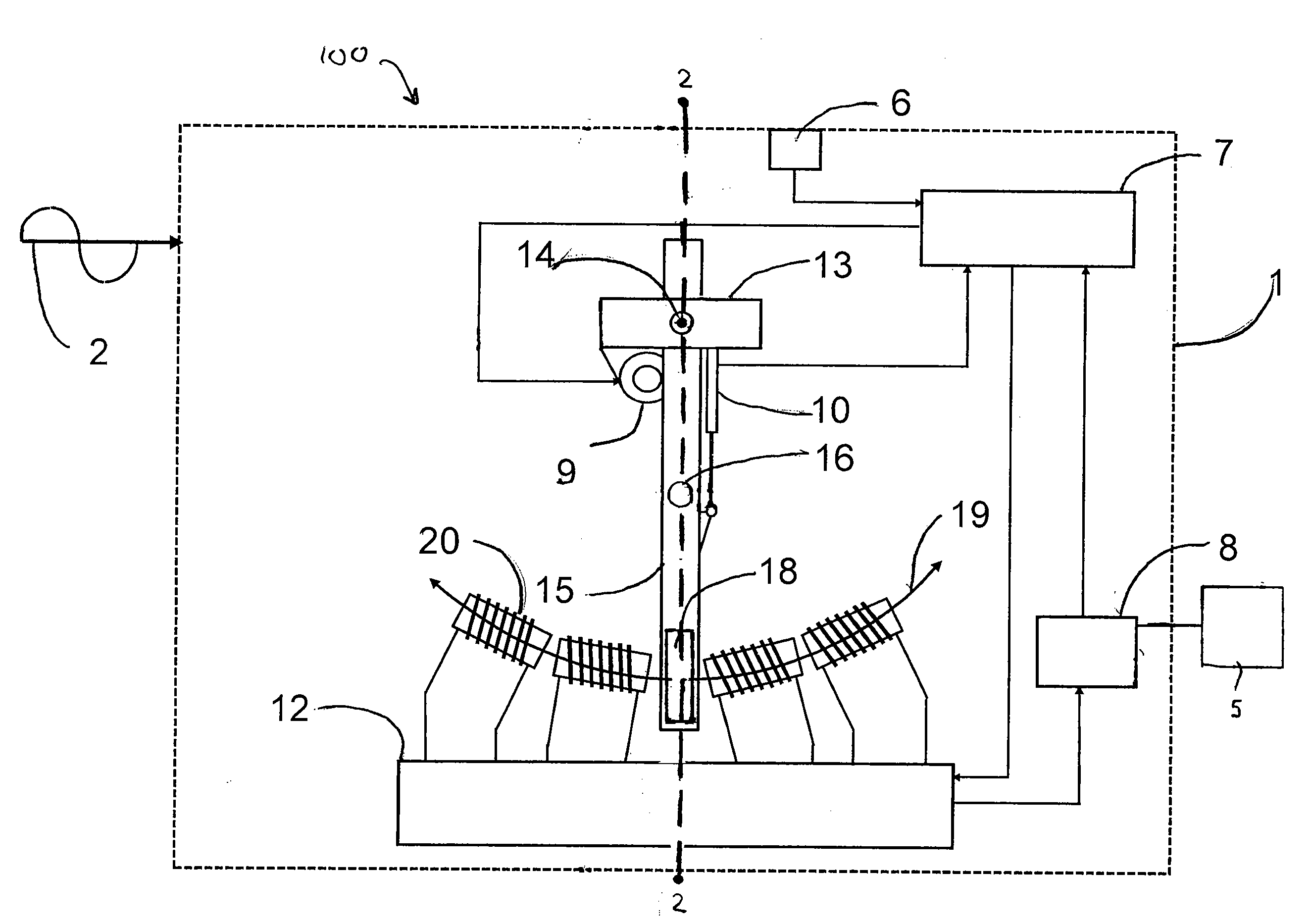
[0071]Referring to FIG. 8, there is shown an isolated side-elevational view of rotor and stator of the present invention. The pendulum 71 is moved up and down by the pendulum adjusting means 68. The pendulum 71 is held within the mounting assembly 66. The pendulum adjusting means 68 adjusts the pendulum 71 up and down within the mounting assembly 66. Bearing 72 connects the mounting assembly 66 to the shell 65. The pendulum 71 imparts oscillatory motion upon the rod 70. The rod 70 oscillates a rotor in the electrical energy converter 67 relative to the stator located in the electrical energy converter 67. A rotation sensor 69 is located adjacent the bearings 72. The amplitude of the motion of the pendulum 71 is controlled by a caliper 27 and brake disk 28 arrangement. Free movement of the pendulum 71 is allowed by the calipers 27 when the calipers 27 do not touch the brake disk 28. If the amplitude of the pendulum 71 needs to be decreased, the calipers 27 press against the brake dis...

sixth embodiment

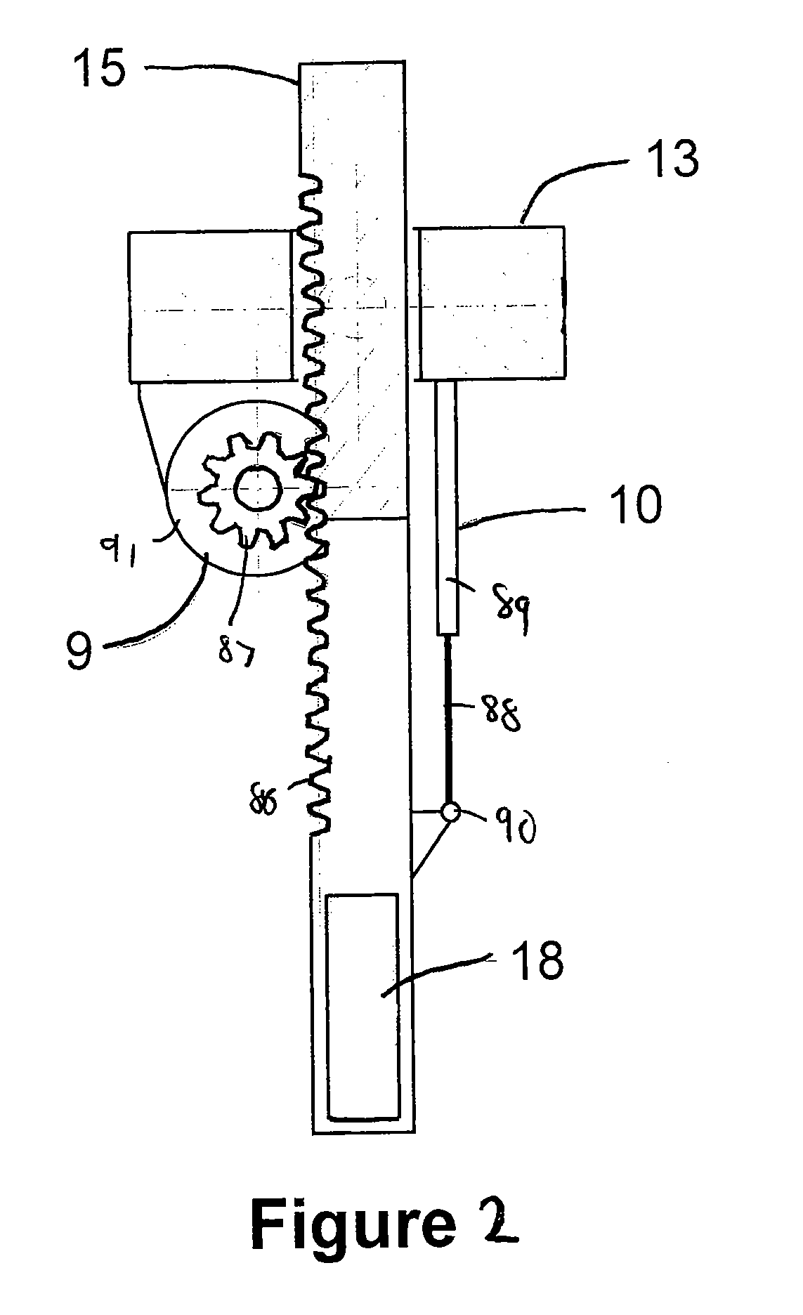
[0074]Referring to FIG. 11, there is shown an isolated side-elevational view of the rotor and stator of the present invention. The pendulum 75 has a split 99 formed therein. Magnets 81 are placed on the walls of the split 99. Magnets 81 pass around the magnets of the variable inductance means 82. The variable inductance means 82 is connected to the shell 76. The pendulum 76 turns rod 80 which turns the rotor relative to the stator in the electrical energy converter 84. A caliber can dampen the motion of the brake disk 85 so as to control the motion of the pendulum 75. The pendulum adjusting means 77 adjusts the height of the pendulum 75. The pendulum adjusting means 77 is mounted to the mounting assembly 79. The bearings 83 are adjacent the mounting assembly 79. Rotation sensor 78 is placed adjacent the bearing 83. The bearings 83 are mounted to the shell 76. The rod 80 oscillates with the pendulum 75 within the bearings 83.


PUM


Abstract

A wave energy converter has a shell, a pendulum pivotally positioned in the shell, a magnet thereon, a variable inductor positioned in the shell, a pendulum adjustor for changing a center of gravity of the pendulum, a motion sensor positioned in the shell, a position sensor connected to the pendulum, a rotation sensor connected to the pendulum, and a controller connected to the motion sensor and the position sensor and the rotation sensor. The pendulum has a magnet thereon. The magnet of the pendulum oscillates adjacent the variable inductor. The variable inductor can adjust the inductive capacity.

Description

CROSS-REFERENCE TO RELATED APPLICATIONS[0001]Not applicable.STATEMENT REGARDING FEDERALLY SPONSORED RESEARCH OR DEVELOPMENT[0002]Not applicable.NAMES OF THE PARTIES TO A JOINT RESEARCH AGREEMENT[0003]Not applicable.INCORPORATION-BY-REFERENCE OF MATERIALS SUBMITTED ON A COMPACT DISC[0004]Not applicable.BACKGROUND OF THE INVENTION[0005]1. Field of the Invention[0006]The present invention relates to the conversion of mechanical energy to electrical energy. More particularly, the present invention the relates to apparatus that convert energy provided by waves in a body of water into electricity. More particularly, the present invention relates to apparatuses utilizing magnetic induction.[0007]2. Description of Related Art[0008]Including Information Disclosed Under 37 CFR 1.97 and 37 CFR 1.98.[0009]With rising oil prices, more and more efforts are being made to find alternative energy sources. Alternative energy sources include biomass (such as biodiesel), geothermal energy, solar energy...

Claims


Application Information

Patent Timeline
Patent Type & Authority Applications(United States)
IPC IPC(8): H02P9/14F03B13/14
CPCF03B13/20F03G7/08F05B2220/708F05B2260/406H02K35/02Y02E10/38H02K7/1892F05B2250/44Y02E10/30
Inventor HOBDY, MILES
Owner HOBDY MILES
Why Eureka
Try Eureka