Touch panel

a touch panel and touch technology, applied in the field of touch panels, can solve the problems of increasing the impedance of the bridge line, disadvantageous to touch sensing signal transmission, and inability to calculate the control circuit, so as to achieve satisfactory touch sensitivity, reduce the resistance, and reduce the line width of the connecting pattern in the intersection region.

Inactive Publication Date: 2010-05-20
WINTEK CORP
View PDF4 Cites 42 Cited by
  • Summary
  • Abstract
  • Description
  • Claims
  • Application Information

AI Technical Summary

Benefits of technology

[0013]In the present invention, the connecting patterns with lower resistivity are disposed in the sensing strings, and therefore the line width of the connecting patterns in the intersection region can be properly reduced. In other words, the parasitic capacitance between the first connecting pattern and the second connecting pattern in the touch panel of the present invention is smaller than that in the prior art. Accordingly, the touch panel of the present invention has satisfactory touch sensitivity. In addition, as the resistivity of the connecting pattern in the present invention is lower, when the line width of the connecting patterns is reduced, the signal transmission of the touch panel is not adversely affected.

Problems solved by technology

In comparison with the parasitic capacitance, the variation in capacitance caused by the user touching the touch panel 100 is probably not sufficiently significant and thus is disadvantageous to calculation of a control circuit.
If the line widths of the first bridge line 124 and the second bridge line 144 are reduced, the impedance of the bridge line will increase, which in turn is disadvantageous to touch sensing signal transmission.

Method used


Image

  • Touch panel
  • Touch panel
  • Touch panel

Examples


first embodiment

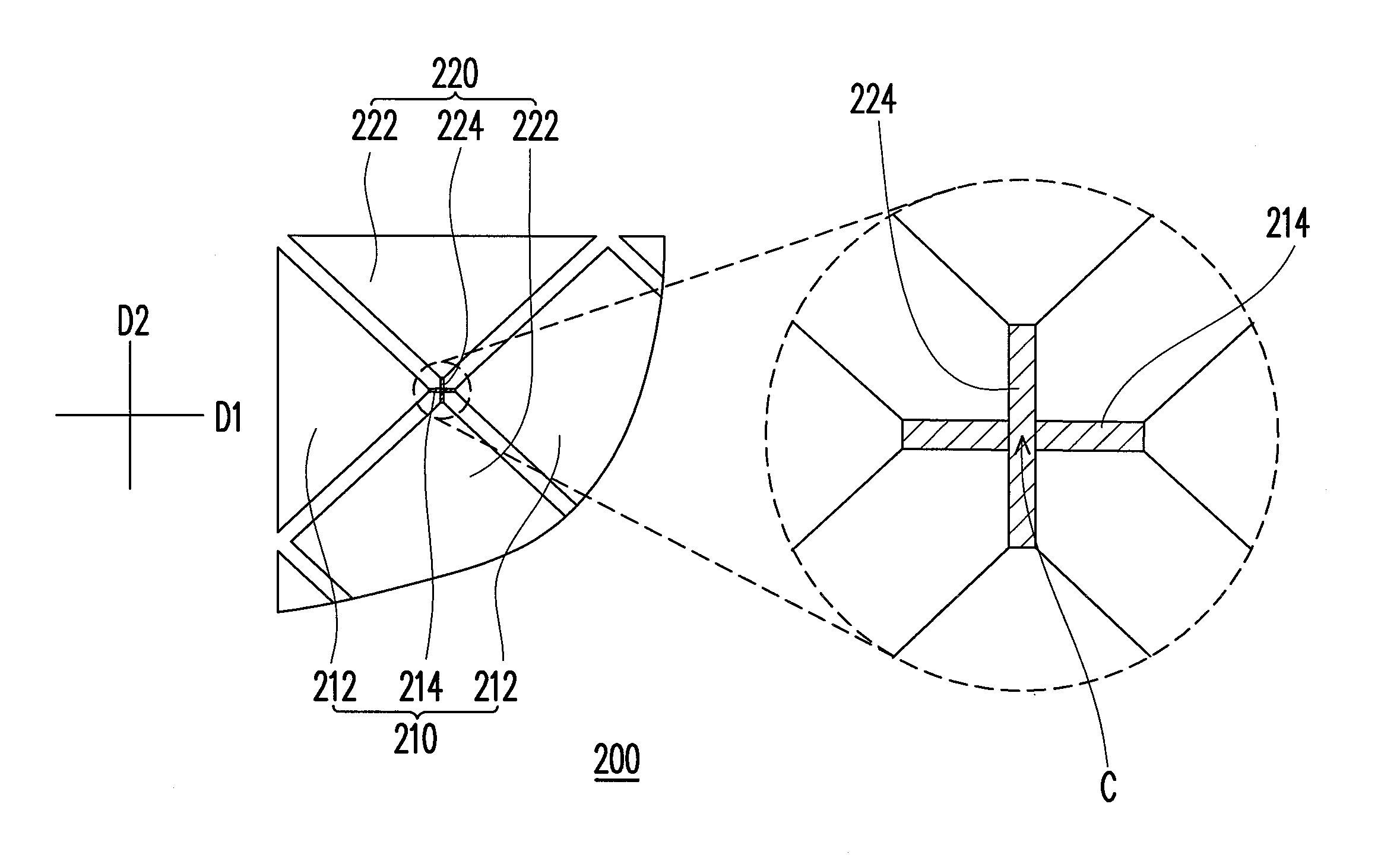
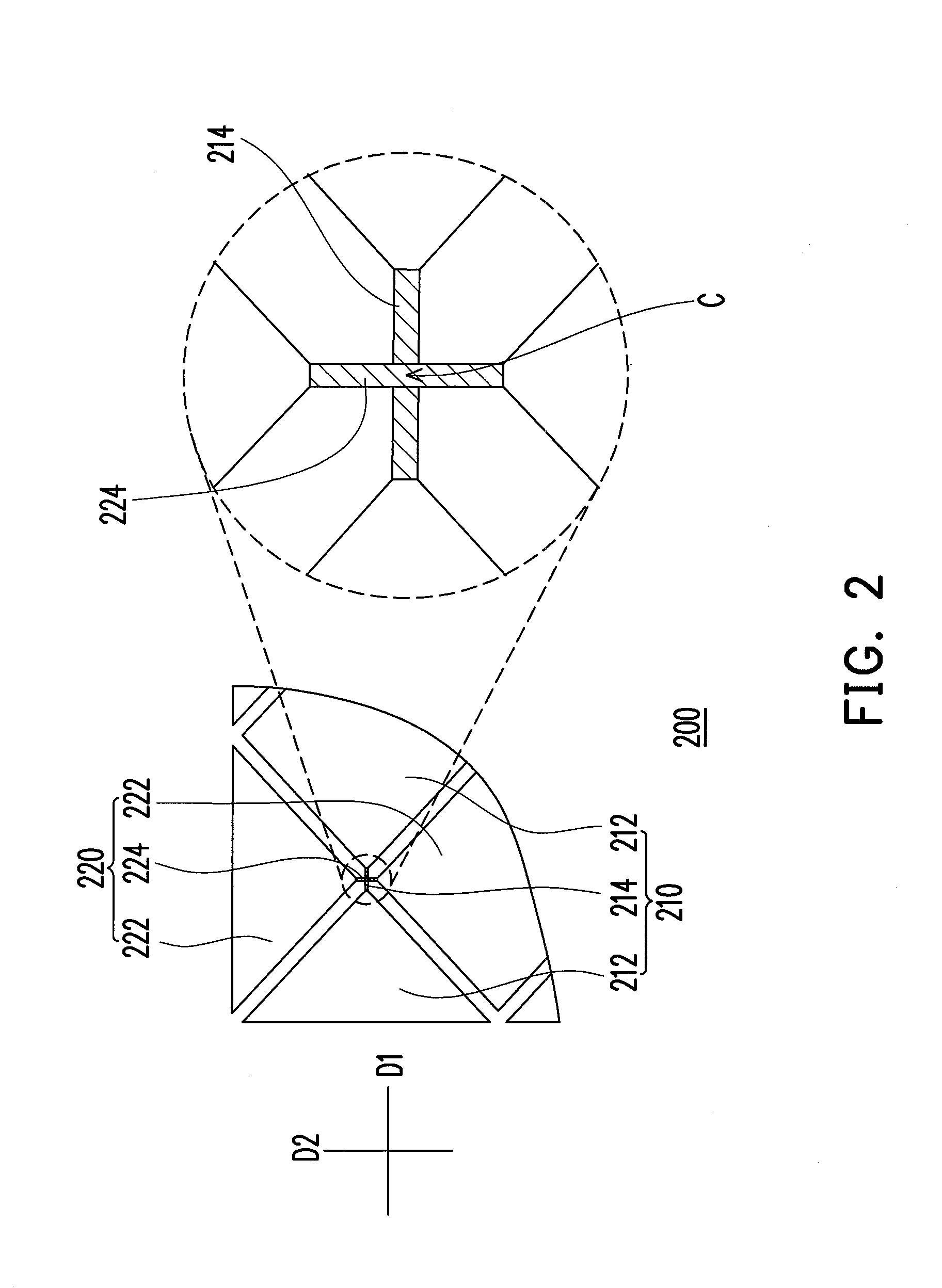
[0020]FIG. 2 shows a touch panel according to the present invention. Referring to FIG. 2, a touch panel 200 has at least one first sensing string 210 and at least one second sensing string 220. The first sensing string 210 is arranged in a first direction D1. The second sensing string 220 does not contact the first sensing string 210 and is arranged in a second direction D2. The first direction D1 is intersected with the second direction D2. In practice, the first direction D1 and the second direction D2 can be perpendicular to each other, or they can be intersected at an angle other than 90 degrees or 0 degree. According to the present embodiment, the first direction D1 and the second direction D2 are perpendicular to each other, for example.

[0021]The first sensing string 210 includes a plurality of first sensing pads 212 and at least one first connecting pattern 214. The first sensing pads 212 are electrically connected with one another. The first connecting pattern 214 is located...

second embodiment

[0029]FIG. 3 shows a touch panel according to the present invention. Referring to FIG. 3, the touch panel 300 is generally the same as the touch panel 200. The first sensing string 210 of the touch panel 300 further includes at least one first auxiliary pattern 216, and the second sensing string 220 further includes at least one second auxiliary pattern 226. The first auxiliary pattern 216 is connected between the first sensing pads 212, and the second auxiliary pattern 226 is connected between the second sensing pads 222.

[0030]In steps of a relevant process of the touch panel 200 or the touch panel 300, the sensing strings 210 and 220 are formed on a substrate (not shown). Herein, adhesion of the low-resistivity metallic materials to the substrate (not shown) is not quite satisfactory. Therefore, in the present embodiment, the first connecting pattern 214 is directly disposed on the first auxiliary pattern 216, and the second connecting pattern 224 is directly disposed on the secon...

third embodiment

[0034]FIG. 4 shows a touch panel according to the present invention. Referring to FIG. 4, a touch panel 400 is substantially derived from the design of the touch panel 300. In the touch panel 400, a first auxiliary pattern 416 is divided into a first section 416A and a second section 416B. A second auxiliary pattern 426 is also divided into a first section 426A and a second section 426B. The line widths of the first sections 416A and 426A are larger than those of the second sections 416B and 426B. In substance, the first sections 416A and 426A are respectively located outside a region where the first connecting pattern 214 and the second connecting pattern 224 are located. The second sections 416B and 426B are respectively located within the region where the first connecting pattern 214 and the second connecting pattern 224 are located.

[0035]The line widths of the second sections 416B and 426B are actually smaller than or equal to those of the first connecting pattern 214 and the se...


PUM


Abstract

A touch panel including at least a first sensing string and at least a second sensing string is provided. The first sensing string arranged in a first direction includes first sensing pads electrically connecting with each other and at least a first connecting pattern. The first connecting patterns are located between two adjacent first sensing pads. The second sensing string does not contact the first sensing string and is arranged in a second direction which crosses with the first direction. The second sensing string includes second sensing pads and at least a second connecting pattern. The second sensing pads electrically connected with one another are located among the first sensing pads. The second connecting pattern is located between two adjacent second sensing pads. Resistivities of the first connecting pattern and the second connecting pattern are lower than those of the first sensing pad and the second sensing pad respectively.

Description

CROSS-REFERENCE TO RELATED APPLICATION[0001]This application claims the priority benefit of Taiwan application serial No. 97144158, filed on Nov. 14, 2008. The entirety of the above-mentioned patent application is hereby incorporated by reference herein and made a part of this specification.BACKGROUND OF THE INVENTION[0002]1. Field of the Invention[0003]The present invention is related to a touch panel, and particularly to a touch panel with higher sensing sensibility.[0004]2. Description of Related Art[0005]FIG. 1 shows a conventional touch panel. To clearly illustrate the device design of the conventional touch panel, FIG. 1 only shows a portion of an enlarged sensing string and omits other possibly present film layers or devices. As shown in FIG. 1, a conventional touch panel 100 includes a plurality of first sensing string 120 and a plurality of second sensing string 140. More specifically, the first sensing string 120 extends in a first direction. Each of the first sensing stri...

Claims


Application Information

Patent Timeline
Patent Type & Authority Applications(United States)
IPC IPC(8): G06F3/041
CPCG06F3/045G06F2203/04111G06F3/0446
Inventor WU, HSIEN-HSINFAN, YUEH-CHICHEN, CHIUNG-CHUANGWENG, RUEY-SHING
Owner WINTEK CORP
Why Eureka
Try Eureka