
Picture signal processing circuit, signal processing method, imaging apparatus, display device, and camera system

a signal processing circuit and picture technology, applied in the field of picture signal processing circuits, can solve the problems of difficult to bring the subject into focus, low focus accuracy, and inability to confirm the picture in original resolution, and achieve the effect of high resolution and easy to bring into focus

Active Publication Date: 2010-05-20
SONY CORP
View PDF1 Cites 1 Cited by
  • Summary
  • Abstract
  • Description
  • Claims
  • Application Information

AI Technical Summary

Benefits of technology

[0011]As described above, when a picture is displayed on the viewfinder monitor, processing of reducing the number of the imaged picture is performed. Accordingly, only by viewing the viewfinder monitor, it may be impossible to confirm the picture in original resolution that has been imaged by the imaging apparatus and the frequency of picture signals. Therefore, it becomes difficult to bring the subject into focus and confirm the subject in focus, and focus accuracy becomes lower.
[0013]Thus, it is desirable that a user can easily bring a subject into focus when imaging a high-resolution picture.
[0020]According to the embodiment of the invention, different picture signals depending on the first or second display mode are output to the display unit and pictures are displayed according to the resolution of the display unit in the second display mode, and thereby, the subject is easily brought into focus. Accordingly, there is an advantage that the subject can be imaged with high resolution.

Problems solved by technology

Accordingly, only by viewing the viewfinder monitor, it may be impossible to confirm the picture in original resolution that has been imaged by the imaging apparatus and the frequency of picture signals.
Therefore, it becomes difficult to bring the subject into focus and confirm the subject in focus, and focus accuracy becomes lower.

Method used


Image

  • Picture signal processing circuit, signal processing method, imaging apparatus, display device, and camera system
  • Picture signal processing circuit, signal processing method, imaging apparatus, display device, and camera system
  • Picture signal processing circuit, signal processing method, imaging apparatus, display device, and camera system

Examples


first embodiment

1. First Embodiment>

External Configuration Example of Imaging Apparatus

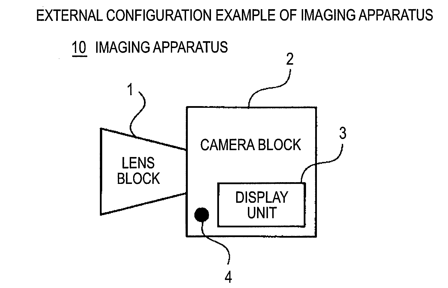
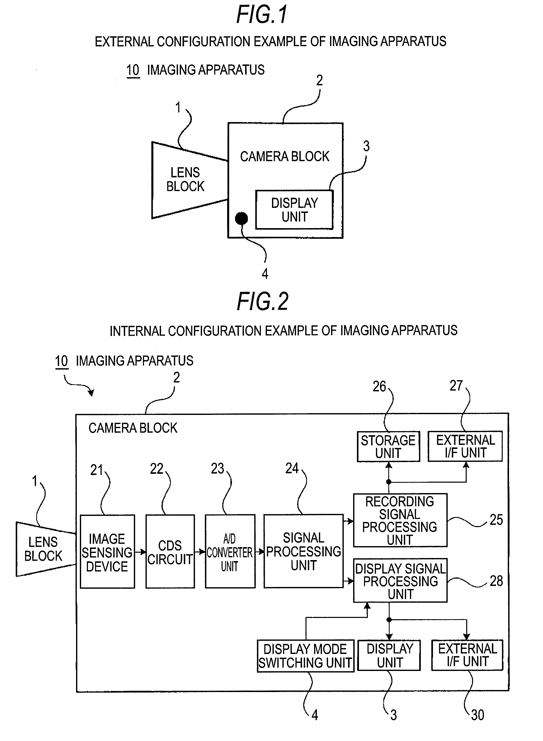
[0036]FIG. 1 shows an external configuration example of an imaging apparatus 10 having a display device.

[0037]The imaging apparatus 10 includes an optical system having a lens, a shutter, etc., and has a lens block 1 that takes subject light into the imaging apparatus 10, and a camera block 2 that generates picture signals from the subject light entering via the lens block 1. Further, the imaging apparatus 10 includes a display unit 3 that displays a picture based on the picture signals generated by the camera block 2 and a display mode switching unit 4 that switches the display mode of the picture to be displayed on the display unit 3 to the first or second display mode. Furthermore, the imaging apparatus 10 includes a display signal processing unit 28, which will be described later, as a picture signal processing circuit.

[0038]The camera block 2 includes an imaging device 21, which will be described later, and ...

second embodiment

2. Second Embodiment

External Configuration Example of Camera System

[0086]Next, the second embodiment according to the invention will be explained with reference to FIGS. 7A to 7C. In the embodiment, an example in which the invention is applied to a camera system that includes the imaging apparatus 10 as a component element will be explained. In the following description, the same signs are assigned to the parts corresponding to those in FIG. 1 that has been already described in the first embodiment and the detailed description thereof will be omitted.

[0087]The location where the display mode switching unit 4 is provided may vary depending on the configuration of the camera system. For example, when the display signal processing unit 28 according to the above described first embodiment and the display mode switching unit 4 are apart from each other, the control signal output from the display mode switching unit 4 by a wired or wireless control device is transmitted to the display sig...

third embodiment

3. Third Embodiment

Internal Configuration Example of First Camera System

[0095]Next, the third embodiment according to the invention will be explained with reference to FIGS. 8 and 9. In the embodiment, an example in which the invention is applied to the first camera system 71 including the imaging apparatus 10 and the display device 75. In the following description, the same signs are assigned to the parts corresponding to those in FIGS. 1 to 3 that have been already described in the first embodiment and the detailed description thereof will be omitted.

[0096]FIG. 8 shows an internal configuration example of the first camera system 71.

[0097]The camera block 2 includes a first display signal processing unit 81 that performs gamma processing or the like on the picture signals supplied from the signal processing unit 24 and interlace-outputs them. The picture signals output by the first display signal processing unit 81 are sent to the display device 75 via the external interface unit 3...


PUM


Abstract

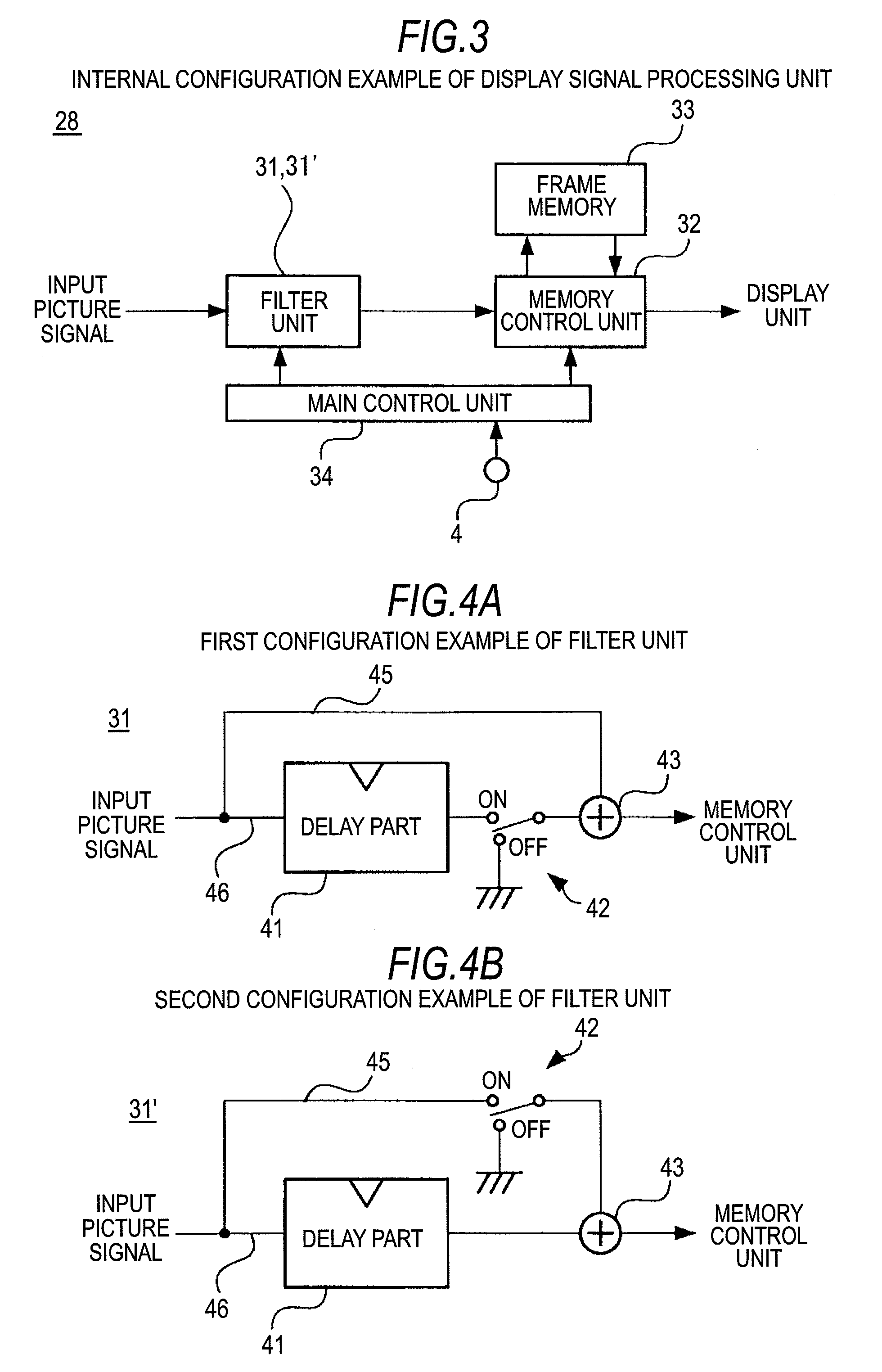
A picture signal processing circuit includes: a filter unit, when, based on first picture signals supplied from an image sensing device that images a subject in a first picture size determined by a first number of pixels, a first or second display mode for display of a picture on a display unit having a picture size determined by a second number of pixels smaller than the first number of pixels is set, that outputs second picture signals obtained by performing filter processing of removing high-frequency components from the first picture signals in the first display mode and outputs the first picture signals without change in the second display mode; a memory control unit that allows a memory to store the first or second picture signals supplied from the filter unit, and reads out the second picture signals from the memory, performs processing of reducing from the first picture size to the second picture size on the second picture signals, and output the signals to the display unit in the first display mode, and reads out the first picture signals corresponding to a picture clipped in the second picture size from the picture in the first picture size from the memory and outputs the signals to the display unit in the second display mode; and a main control unit that controls switching between the first and second picture signals filter-processed or read out from the memory by the memory control unit according to a command of switching between the first and second display modes provided by a display mode switching unit that provides the command of switching between the first and second display modes.

Description

BACKGROUND OF THE INVENTION[0001]1. Field of the Invention[0002]The present invention relates to a picture signal processing circuit, a picture signal processing method, an imaging apparatus, a display device, and a camera system that are preferable when they are applied to the case of imaging high-resolution pictures, for example.[0003]2. Background Art[0004]Recently, with improvements in performance of imaging devices such as imaging sensors, the number of pixels in pictures imaged using an imaging apparatus such as a video camera or a still camera has been increased. Typically, a photographer brings a subject into focus while looking into a small viewfinder monitor provided on or connected to the imaging apparatus, and takes an image of the subject. However, since the display range of the viewfinder monitor is small, the number of displayed pixels of the viewfinder monitor is smaller than the number of effective pixels of the imaging device. Accordingly, for display of pictures o...

Claims


Application Information

Patent Timeline
Patent Type & Authority Applications(United States)
IPC IPC(8): H04N5/217H04N5/222H04N5/225
CPCH04N5/23229H04N5/23245H04N5/775H04N5/2628H04N5/772H04N5/23293H04N23/667H04N23/80H04N23/63
Inventor NAKASHIMA, YASUTAKA
Owner SONY CORP
Learn More