Ceramic electronic component

a technology of electronic components and ceramics, applied in the direction of fixed capacitor details, inorganic insulators, fixed capacitors, etc., can solve problems such as cracks in ceramic electronic components

Active Publication Date: 2010-05-20
MURATA MFG CO LTD
View PDF5 Cites 22 Cited by
  • Summary
  • Abstract
  • Description
  • Claims
  • Application Information

AI Technical Summary

Benefits of technology

[0015]Preferred embodiments of the present invention provide a structure of an external te...

Problems solved by technology

This leads to a risk that the ceramic electronic component may crack when being mounted or during use.
However, the e...

Method used


Image

  • Ceramic electronic component
  • Ceramic electronic component
  • Ceramic electronic component

Examples


Embodiment Construction

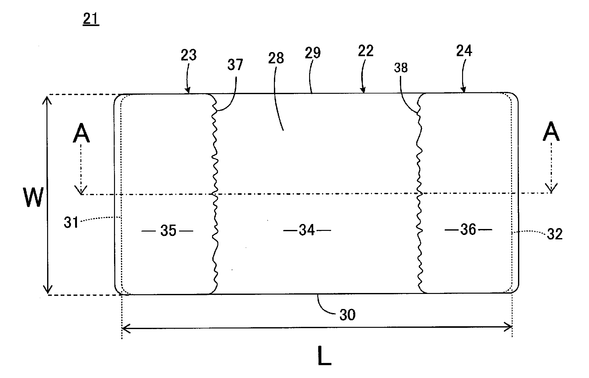
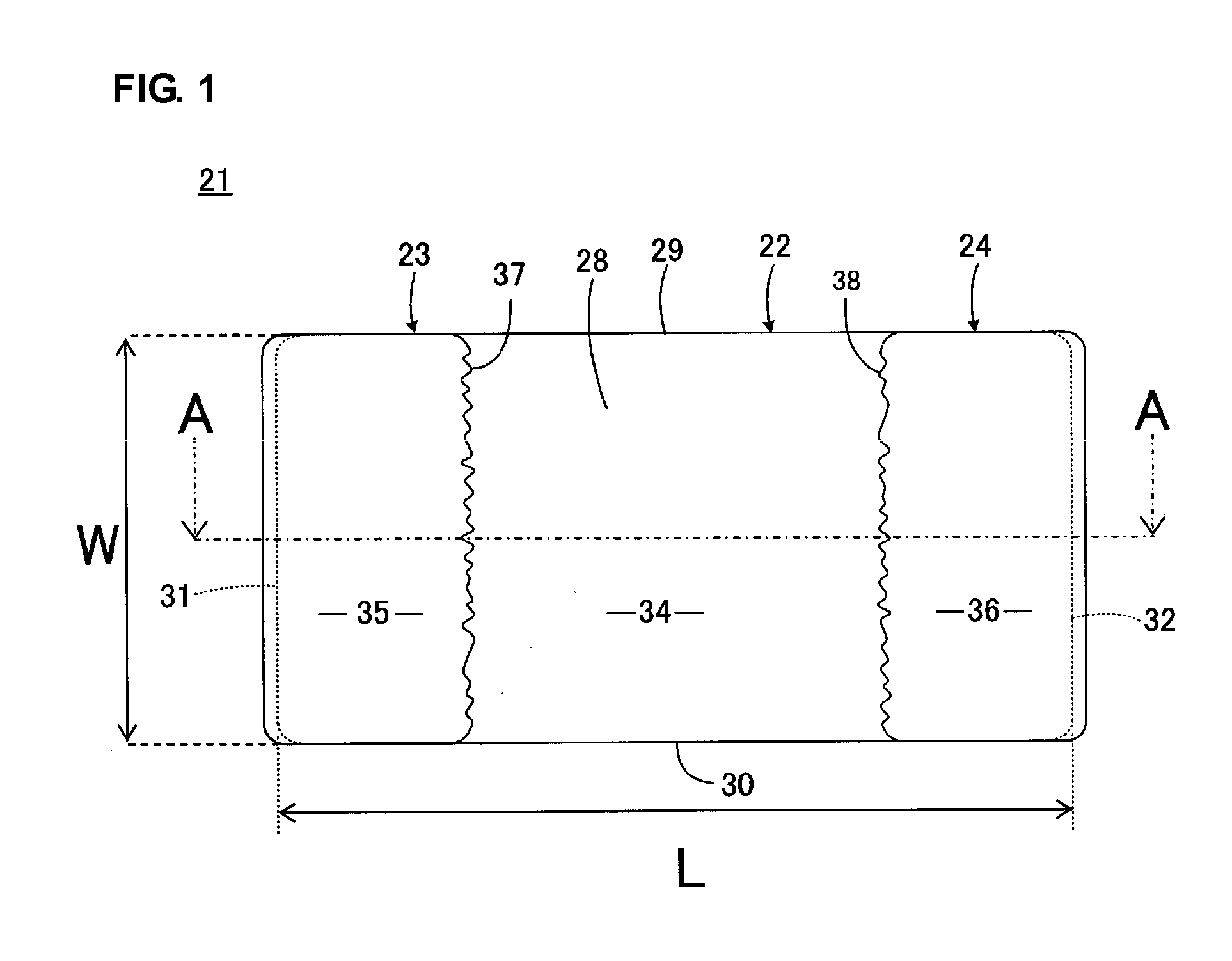
[0050]FIGS. 1 to 4 illustrate a first preferred embodiment of the present invention. FIG. 1 is a bottom view of a multilayer ceramic capacitor 21 as one example of a ceramic electronic component according to the first preferred embodiment of the present invention. FIG. 2 is a side view of the multilayer ceramic capacitor 21, and FIG. 3 is a sectional view taken along a line III-III in FIG. 1. The multilayer ceramic capacitor 21 includes a ceramic element body 22. FIG. 4 is a plan view illustrating an internal structure of the ceramic element body 22.

[0051]The multilayer ceramic capacitor 21 includes, in addition to the ceramic element body 22, first and second external terminal electrodes 23 and 24 and first and second internal terminal electrodes 25 and 26.

[0052]The ceramic element body 22 has a first principal surface 27 and a second principal surface 28 arranged to face each other, a first lateral surface 29 and a second lateral surface 30 arranged to face each other, and a first...


PUM

PropertyMeasurementUnit
Thicknessaaaaaaaaaa
Shapeaaaaaaaaaa
Dimensionaaaaaaaaaa

Abstract

In a ceramic electronic component having a thin structure, the occurrence of cracks due to stress applied when the ceramic component is being mounted or in a mounted state are prevented. Each of first and second external terminal electrodes has a substantially rectangular region on a principal surface of a ceramic element body, the principal surface being directed to the mounting surface side. An end of the first external terminal electrode, which is arranged in contact with a gap region, and an end of the second external terminal electrode, which is positioned in contact with the gap region, each preferably have a concave-convex shape on the principal surface.

Description

BACKGROUND OF THE INVENTION[0001]1. Field of the Invention[0002]The present invention relates to a ceramic electronic component, and more particularly, to a structure of an external terminal electrode, which is provided in a ceramic electronic component.[0003]2. Description of the Related Art[0004]Recently, with a reduction in size and thickness of electronic devices such as cell phones and portable music players, the size and the thickness of a ceramic electronic component disposed in those electronic devices have also been reduced at a high pitch. While the ceramic electronic component is usually mounted on a wiring board disposed inside the electronic device, the strength of the ceramic electronic component itself tends to lower because of the reduction in size and thickness of the ceramic electronic component. This leads to a risk that the ceramic electronic component may crack when being mounted or during use. Such a point will be described in more detail below.[0005]FIG. 16 is...

Claims


Application Information

Patent Timeline
IPC IPC(8): H01G4/228
CPCH01G4/232H01B3/12H01G4/12
Inventor NISHISAKA, YASUHIROSANADA, YUKIOSATO, KOJIONISHI, KOSUKE
Owner MURATA MFG CO LTD
Why Eureka
Try Eureka