Terminal structure of an electronic component

a technology of electronic components and terminal structures, which is applied in the direction of printed circuits, electrical apparatus, casings/cabinets/drawers of electrical apparatus, etc., can solve the problems of unstable fitting posture with respect to the circuit board, dimension error of manufactured components, and inability to play between pin headers and press portions, etc., to achieve a large contact area, prevent the effect of pin header tilting and increase assembly strength

Inactive Publication Date: 2010-05-20
SHARP KK
View PDF1 Cites 6 Cited by
  • Summary
  • Abstract
  • Description
  • Claims
  • Application Information

AI Technical Summary

Benefits of technology

[0014]Moreover, according to the invention, in the terminal structure of an electronic component, an end part of the guide axis that projects out of the insertion hole is connected to a conductor of the printed circuit board. With this structure, it is possible to enhance assembly strength between the case frame and the printed circuit board. In addition, it is possible to form the guide axis and the case frame from material with good heat and electrical conductions and, by connecting them with the conductor of the board, use the case frame as a heat dissipation conductor or grounding conductor.
[0015]Moreover, according to the invention, in the terminal structure of an electronic component, a lengthened portion is provided on the upper surface of the pin header so as to face one or either side of the press portion with respect to the length direction of the pin header, the lengthened portion being close to the press portion. With this structure, even if tilting occurs during fixing of the pin header, the lengthened portion provided on the upper surface of the pin header makes contact with the press portion to serve as a guide, and thus it is possible to control the tilting.
[0016]Moreover, according to the invention, in the terminal structure of an electronic component, as the guide hole, a plurality of them are provided in the pin header along its length direction, and the lengthened portion has a width large enough to face the guide axis. With this structure, the pin header, even an elongated one, is pressed down via the press portion with the plurality of places along its length direction serving as a guide; thus, it is possible to fix the pin he...

Problems solved by technology

When a pin header having a plurality of pin terminals is mounted on a circuit board, if it is fixed by use of a case, unstableness may occur for the play between the pin header and a press portion of the case, or for the dimension error of the manufactur...

Method used


Image

  • Terminal structure of an electronic component
  • Terminal structure of an electronic component
  • Terminal structure of an electronic component

Examples


first embodiment

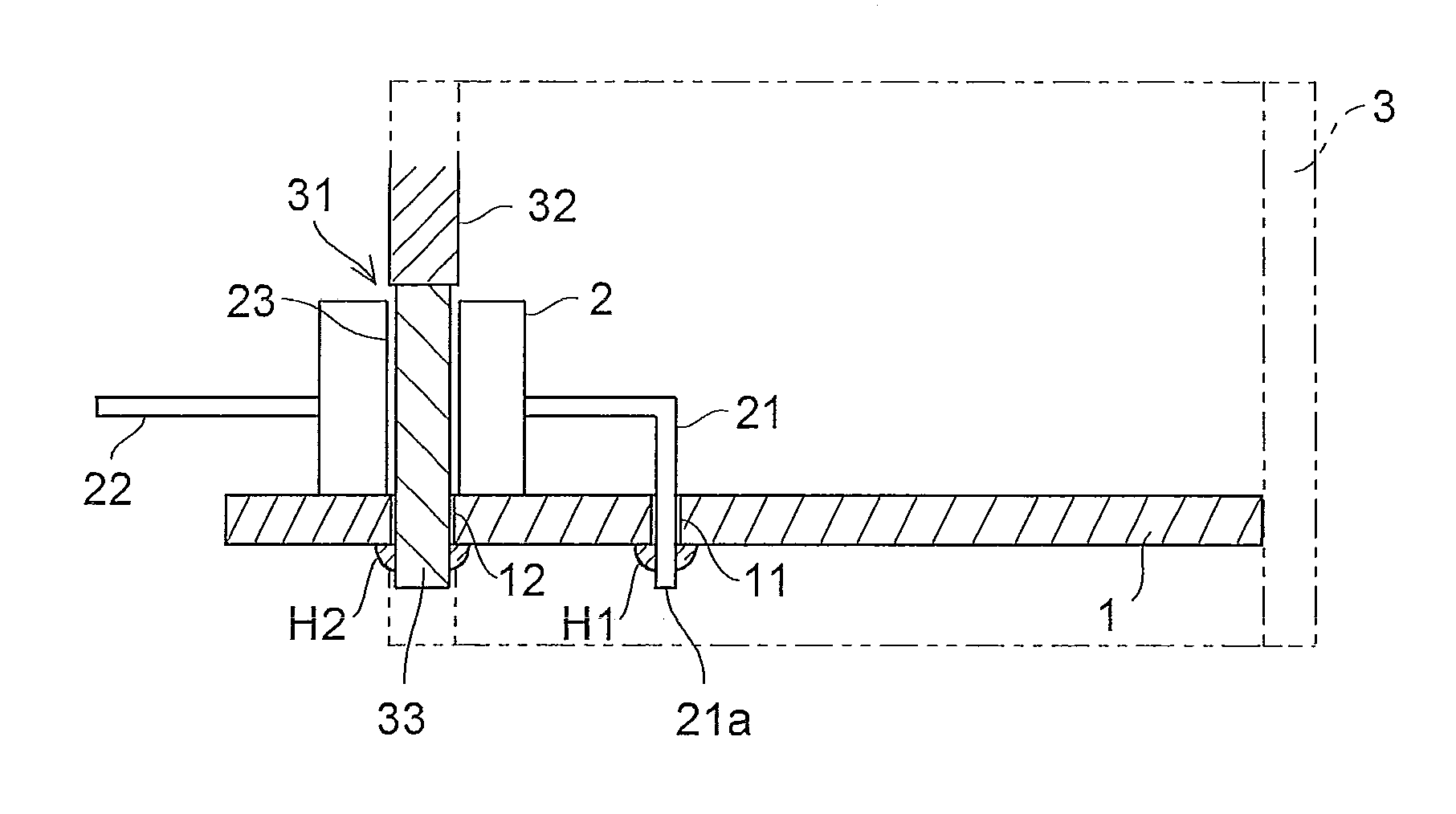
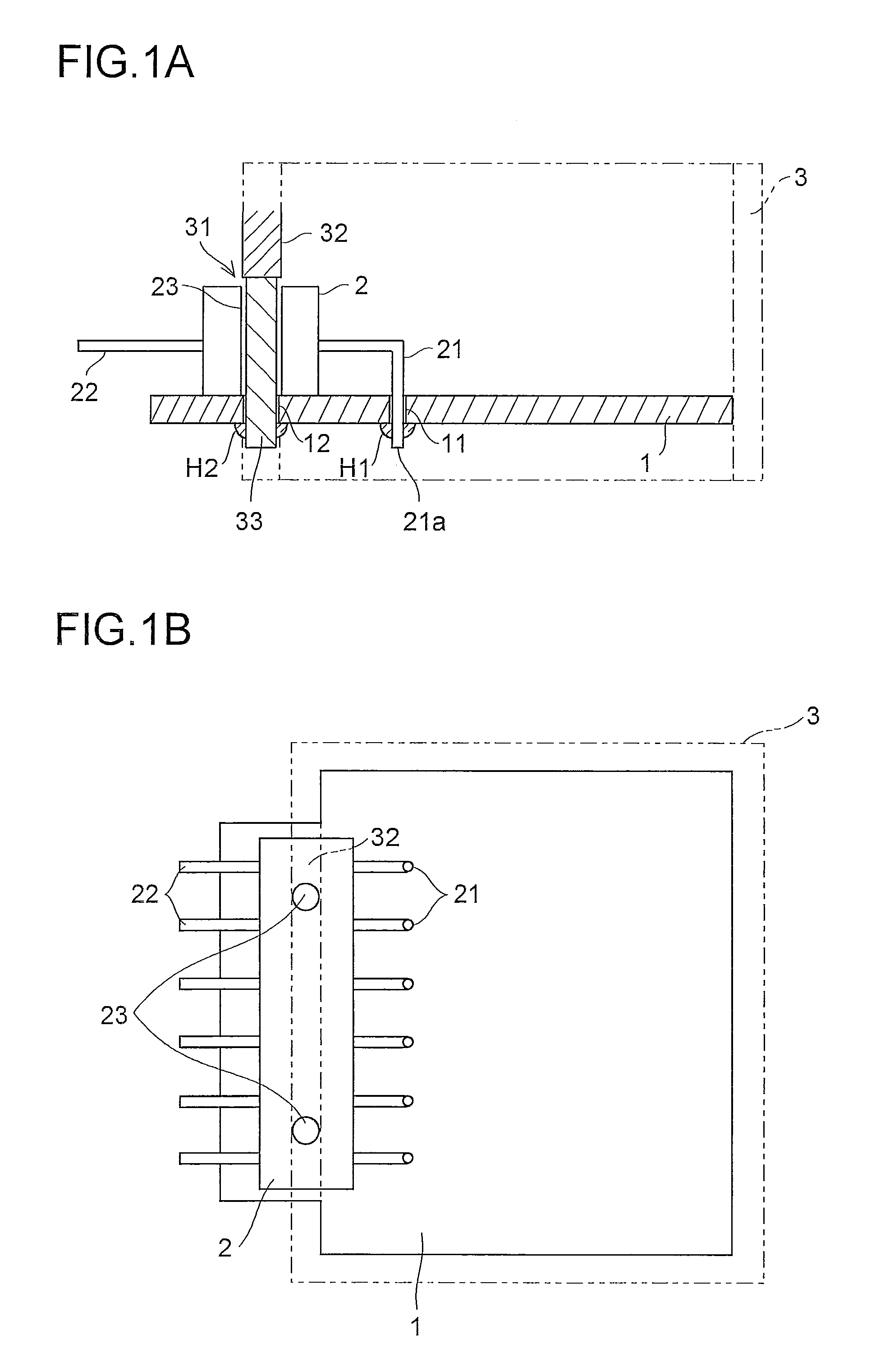
[0024]First, a terminal structure of an electronic component will be described with reference to FIG. 1.

[0025]FIG. 1A shows a terminal structure in which, on mounting an electronic component (for example, a pin header 2) on a printed circuit board 1, an end part 21a of a pin terminal 21, which is bent into an L-shape and provided on one side of the pin header 2, is inserted into a through hole 11 provided in the printed circuit board 1 to penetrate there through and project out of the opposite surface, and is then soldered with a solder H1 to be fixed; a pin terminal 22 provided on the other side is made to project out of a notch opening 31 provided in a side wall of a case frame 3.

[0026]To secure connection with external electronic devices and electronic components, the pin terminal 22 projecting out of the case frame 3 needs to be accurately arranged and positioned with a correct posture, and thus accuracy in fixing them to a predetermined position with a predetermined posture wi...

second embodiment

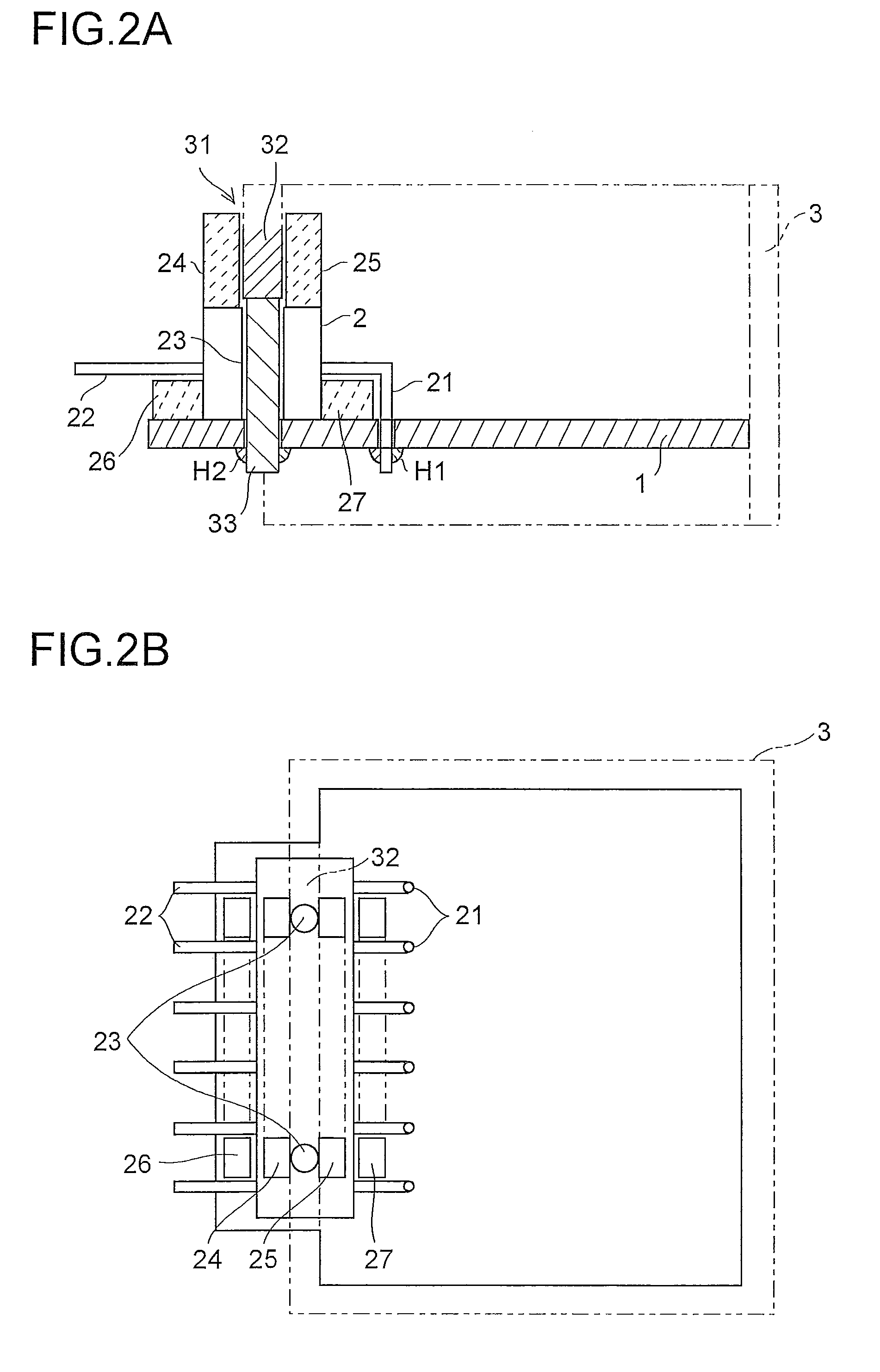
[0036]Next, a terminal structure of an electronic component that allows further accurate positioning and fixing will be described with reference to FIGS. 2 and 3.

[0037]As shown in FIGS. 2A and 2B, compared with the terminal structure of an electronic component according to the first embodiment, that according to the second embodiment differs in that lengthened portions 24 and 25 and extended portions 26 and 27 of which all serve as a supporting guide portion for preventing the tilting of the pin header 2 further accurately are additionally provided.

[0038]The tilting of the pin header 2 can be prevented, for example, by providing the lengthened portion 24 or / and 25 on the upper surface of the pin header 2 so as to face one or either side of the press portion 32 with respect to the length direction of the pin header, the lengthened portion being close to the press portion 32. The lengthened portions 24 and 25 may have a shape and be of any number so long as they exhibit, when the pin...


PUM


Abstract

The invention relates to a terminal structure of an electronic component, such as a tuner, in which a printed circuit board 1 on which electronic components including a pin header 2 having a plurality of pin terminals, and a case frame 3 housing the printed circuit board and having a notch opening exposing the pin terminals are provided. A guide hole 23 that penetrates from the upper surface of the pin header 2 to its lower surface in contact with the printed circuit board, and a guide axis 33—insertable into the guide hole 23—provided in a press portion 32 are provided, such that the pin header is held between the press portion 32 provided in the case frame 3 and the printed circuit board, enabling the pin header, even a slim, compact one, having a plurality of pin terminals to be fixed accurately to a predetermined position on the board with a predetermined posture.

Description

[0001]This application is based on Japanese Patent Application No. 2008-292960 filed on Nov. 17, 2008, the contents of which are hereby incorporated by reference.BACKGROUND OF THE INVENTION[0002]1. Field of the Invention[0003]The present invention relates to a terminal structure of an electronic component such as a tuner.[0004]2. Description of Related Art[0005]Owing to slim liquid crystal television sets, there are needs for slim, compact electronic devices for incorporation in liquid crystal television sets etc. Incidentally, electronic devices such as tuners have a circuit board, on which various electronic components and electric circuits are mounted, housed in a case, and have pin terminals for external connection projecting outside the case through predetermined holes provided in the case.[0006]To secure connection with external electronic devices and electronic components, the arrangement position of the pin terminals projecting outside the case needs to be accurate, and acco...

Claims


Application Information

Patent Timeline
IPC IPC(8): H05K5/00
CPCH05K3/301H05K3/3447H05K5/0247H05K2201/105H05K2201/10189H05K2201/10424H05K9/006
Inventor KATAGIRI, YOSHITAKAKITAGUCHI, MASANORI
Owner SHARP KK
Why Eureka
Try Eureka