
Reactor vessel reflector with integrated flow-through

Active Publication Date: 2010-05-20
NUSCALE
View PDF7 Cites 12 Cited by
  • Summary
  • Abstract
  • Description
  • Claims
  • Application Information

AI Technical Summary

Benefits of technology

[0018]A power module is disclosed herein, as comprising a reactor core and a reflector partially surrounding the reactor core to improve a neutron efficiency of the power module. The reflector comprises one or more inlets located adjacent the reactor core, wherein the one or more inlets are configured to receive coolant that has passed through at least a portion of the reactor core prior to entering the one or more inlets.

Problems solved by technology

As a result of the close proximity of the reflector to the reactor core, the reflector tends to heat up.

Method used


Image

  • Reactor vessel reflector with integrated flow-through
  • Reactor vessel reflector with integrated flow-through
  • Reactor vessel reflector with integrated flow-through

Examples


Embodiment Construction

[0022]Various embodiments disclosed or referred to herein may be operated consistent, or in conjunction, with features found in co-pending U.S. application Ser. No. 11 / 941,024 which is herein incorporated by reference in its entirety.

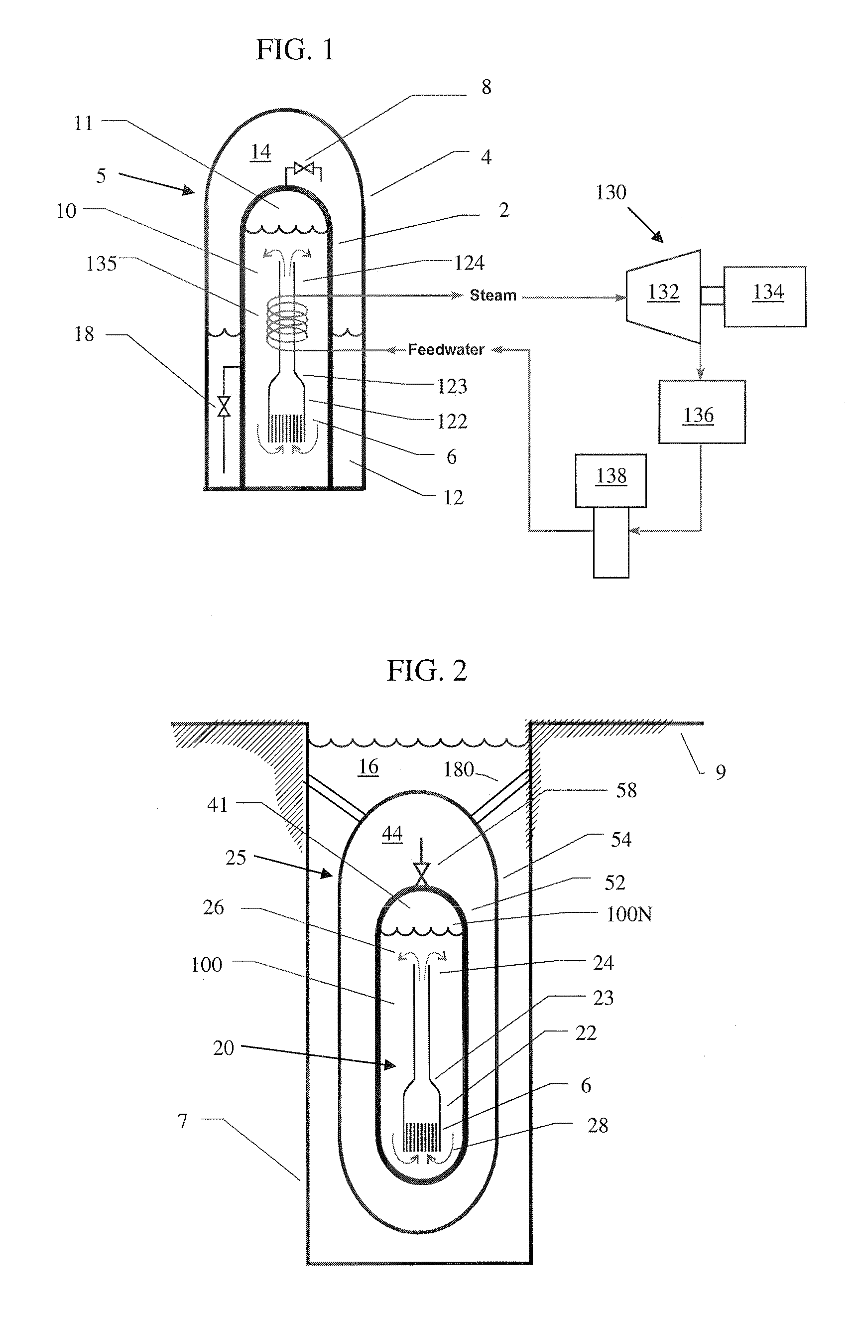
[0023]FIG. 2 illustrates a power module assembly 25 comprising an internally dry containment vessel 54. The containment vessel 54 is cylindrical in shape, and has ellipsoidal, domed or hemispherical upper and lower ends. The entire power module assembly 25 may be submerged in a pool of water 16 which serves as an effective heat sink. The containment vessel 54 may be welded or otherwise sealed to the environment, such that liquids and gas do not escape from, or enter, the power module assembly 25. The containment vessel 54 may be supported at any external surface.

[0024]In one embodiment, the containment vessel 54 is suspended in the pool of water 16 by one or more mounting connections 180. The pool of water 16 and the containment vessel 54 may further be...


PUM


Abstract

A nuclear reactor module includes a reactor core and a reactor housing that surrounds the reactor core about its sides, wherein the reactor housing is configured to direct coolant through the reactor core. A neutron reflector is located between the reactor core and the reactor housing, wherein the neutron reflector has a plurality of inlet ports facing the reactor core. The neutron reflector also has a plurality of outlet ports fluidly connected to the inlet ports to direct a portion of the coolant through the neutron reflector.

Description

TECHNICAL FIELD[0001]The invention relates to the field of nuclear power generation, including systems designed to cool a reactor core.BACKGROUND[0002]In nuclear reactors designed with passive operating systems, the laws of physics are employed to ensure that safe operation of the nuclear reactor is maintained during normal operation or even in an emergency condition without operator intervention or supervision, at least for some predefined period of time. A nuclear reactor 5 includes a reactor core 6 surrounded by a reactor vessel 2. Water 10 in the reactor vessel 2 surrounds the reactor core 6. The reactor core 6 is further located in a shroud 122 which surround the reactor core 6 about its sides. When the water 10 is heated by the reactor core 6 as a result of fission events, the water 10 is directed from the shroud 122 and out of a riser 124. This results in further water 10 being drawn into and heated by the reactor core 6 which draws yet more water 10 into the shroud 122. The ...

Claims


Application Information

Patent Timeline
IPC IPC(8): G21C15/10G21C11/06
CPCG21C1/322G21C15/10Y02E30/40G21C15/26G21C15/16Y02E30/30G21C1/32G21C5/00
Inventor YOUNG, ERIC PAUL
Owner NUSCALE
Features
  • Generate Ideas
  • Intellectual Property
  • Life Sciences
  • Materials
  • Tech Scout
  • Unparalleled Data Quality
  • Higher Quality Content
  • 60% Fewer Hallucinations
Learn More