Multi-connector apparatus with connection-sequencing interlock mechanism

Active Publication Date: 2010-05-20
DELPHI TECH IP LTD
View PDF8 Cites 1 Cited by
  • Summary
  • Abstract
  • Description
  • Claims
  • Application Information

AI Technical Summary

Benefits of technology

[0004]The present invention is directed to a connection system including a multi-bay connector header and an improved connection-sequencing interlock plate integrated into the connector header. The interlock plate covers portions of the connector header, and can move with respect to the connector header to prevent access to selected bays of the connector header. A detent lock feature retains the interlock plate in a base position that allows insertion of one or more make-first/break-last connectors, but blocks insertion of one or more make-last/break-first connectors. Once the make-first/break-last connector(s) is ins

Problems solved by technology

The main drawback with known connection-sequencing interlock mechanisms is that they tend to be application specific and require custom-produced connectors, which can significantly increase system cost.

Method used


Image

  • Multi-connector apparatus with connection-sequencing interlock mechanism
  • Multi-connector apparatus with connection-sequencing interlock mechanism
  • Multi-connector apparatus with connection-sequencing interlock mechanism

Examples


Embodiment Construction

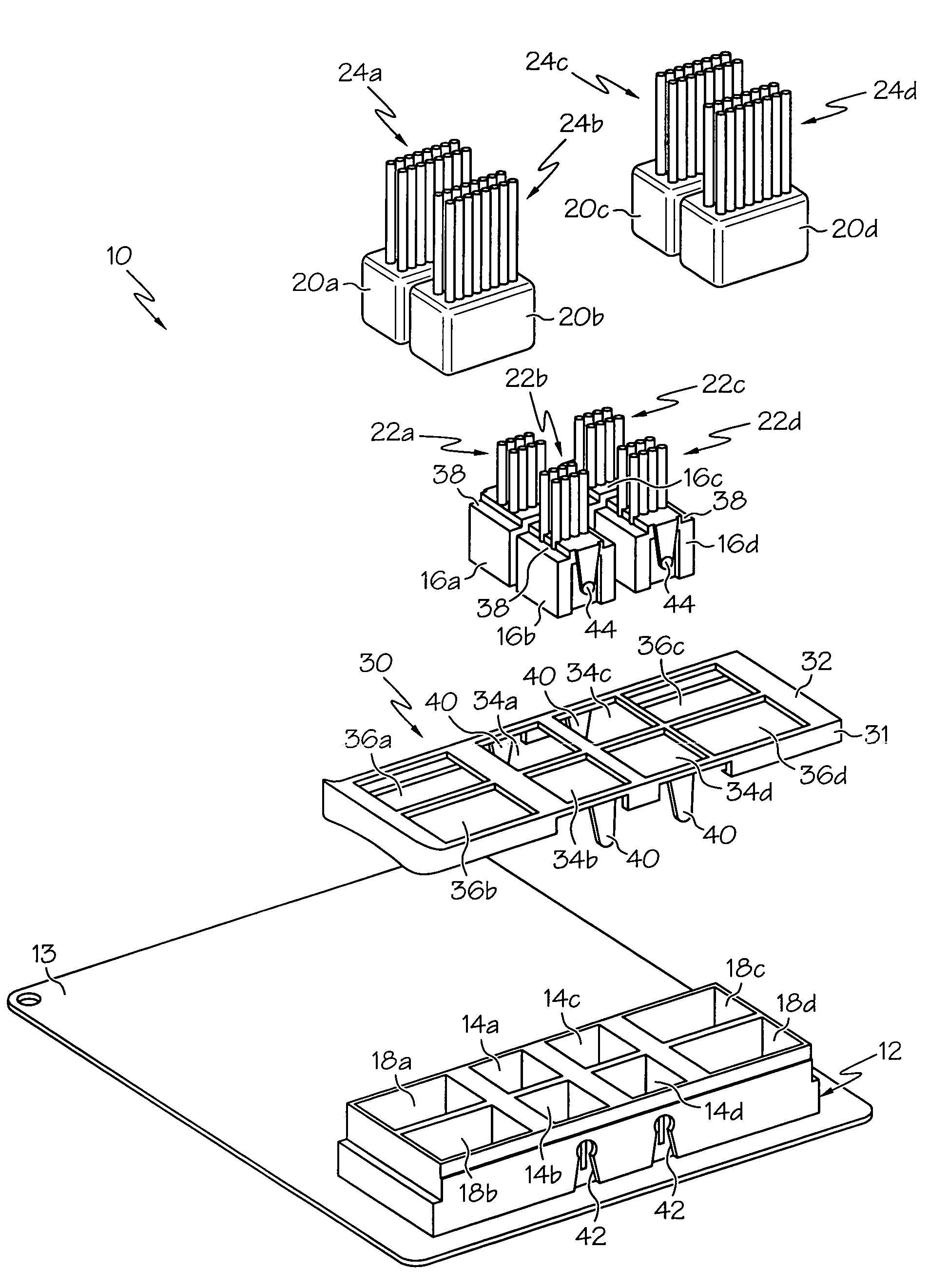
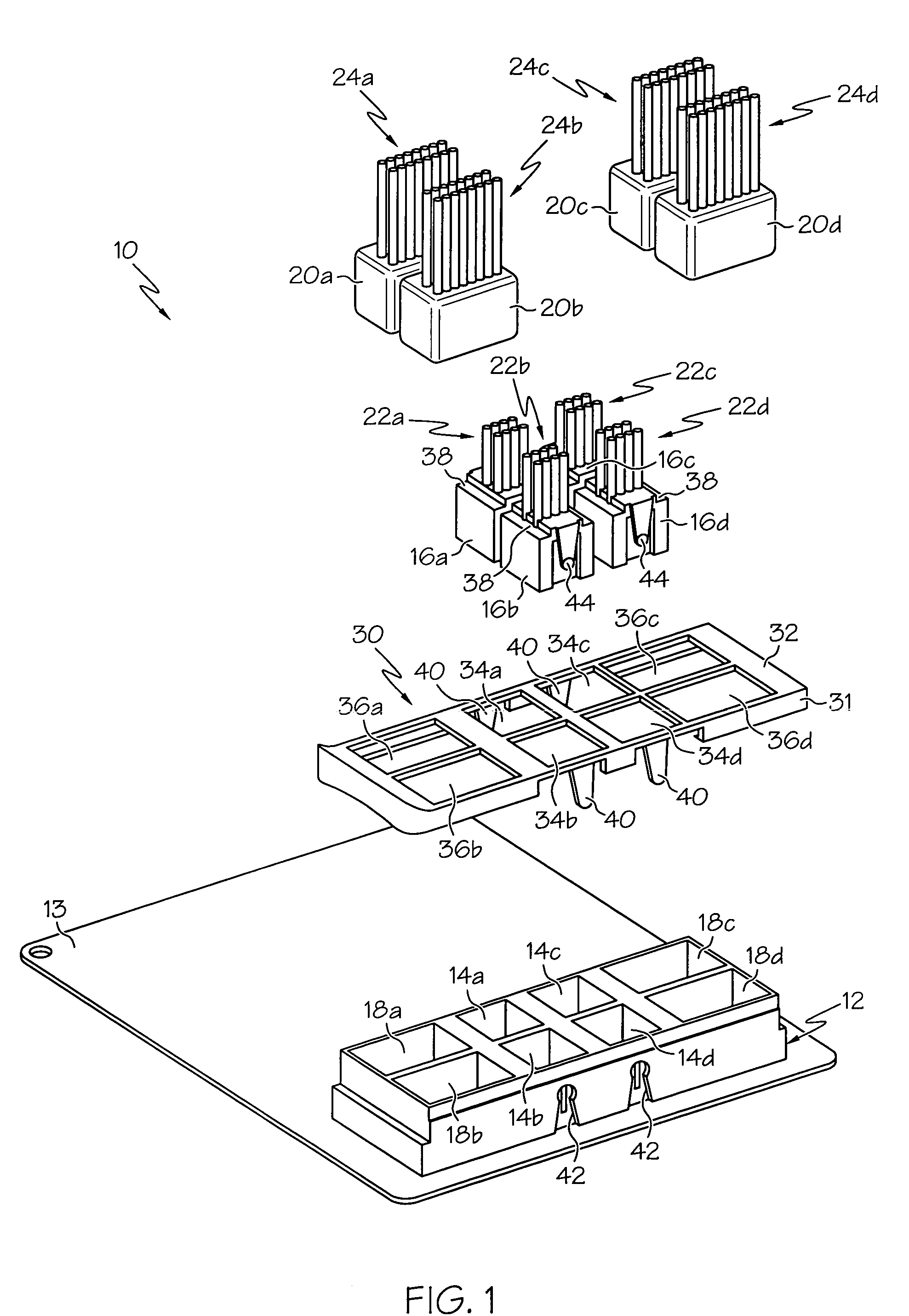
[0010]The apparatus of the present invention is disclosed herein in the context of a connection system 10 for a high voltage vehicle electrical system, including a multi-bay male-pin connector header 12 configured to receive multiple plug-in female connectors. In the illustrated embodiment, the connector header 12 is mounted on a circuit board 13, but it should be understood that the connector header 12 may alternatively be integrated into a larger component such as the housing of a battery pack, if desired. Moreover, the connection system 10 may be used in various other applications, both vehicular and non-vehicular.

[0011]Referring to the exploded view of FIG. 1, the illustrated connector header 12 includes a set of four high-voltage bays 14a, 14b, 14c, 14d configured to receive four high-voltage female power connectors 16a, 16b, 16c, 16d, and a set of four low-voltage bays 18a, 18b, 18c, 18d configured to receive four female signal connectors 20a, 20b, 20c, 20d. The connector pins...


PUM


Abstract

An interlock plate slidably affixed to a multi-bay connector header ensures a preordained connection sequence of multiple plug-in connectors. The interlock plate covers portions of the connector header, and can move with respect to the connector header to prevent access to selected bays of the header. When in a base position, the interlock plate allows insertion of one or more make-first / break-last connector plugs, but blocks insertion of one or more make-last / break-first connector plugs. When in a shifted position, the interlock plate prevents removal of the inserted make-first / break-last connector plug(s), and allows insertion of the make-last / break-first connector plug(s). Insertion of the make-last / break-first connector plug(s) locks the interlock plate in the shifted position, so that the make-last / break-first connector plug(s) must be removed prior to the make-first / break-last connector plug(s).

Description

TECHNICAL FIELD[0001]The present invention is directed to connection systems including multiple plug-in connectors, and more particularly to an interlock mechanism for ensuring that the plug-in connectors are inserted in a specified sequence and removed in the opposite sequence.BACKGROUND OF THE INVENTION[0002]In an electrical system including multiple components or modules that are interconnected with cables and plug-in connectors, separate sets of cables and connectors are generally used for power and signal, and the order or sequence in which the power and signal connectors are to be inserted and removed is sometimes specified in order to prevent component damage and / or ensure technician safety. For example, some high-voltage components include a multi-bay connector header for receiving both a high-voltage power connector and a low-voltage signal connector, and an interlock mechanism for ensuring that the power connector is inserted prior to insertion of the signal connector, and...

Claims


Application Information

Patent Timeline
IPC IPC(8): H01R13/62
CPCB60L3/0069B60L3/04H01R2201/26H01R13/64H01R13/639
Inventor BEER, ROBERT C.
Owner DELPHI TECH IP LTD
Why Eureka
Try Eureka