Acetabular cup with supplemental screw fixation using conical interference fit between screw and cup

Inactive Publication Date: 2010-05-20
URE KEITH J
View PDF3 Cites 2 Cited by
  • Summary
  • Abstract
  • Description
  • Claims
  • Application Information

AI Technical Summary

Problems solved by technology

These techniques at times do not achieve adequate fixation, and cup malpositioning or “spin-out” is not uncommon.
While these measures allow for better stabilization, they give rise

Method used


Image

  • Acetabular cup with supplemental screw fixation using conical interference fit between screw and cup
  • Acetabular cup with supplemental screw fixation using conical interference fit between screw and cup
  • Acetabular cup with supplemental screw fixation using conical interference fit between screw and cup

Examples


Embodiment Construction

[0008]Fixation arrangements for joint implants and the like are discussed.

[0009]Those of ordinary skill in the art will realize that the following detailed description of the present invention is illustrative only and is not intended to be in any way limiting. Other embodiments of the present invention will readily suggest themselves to such skilled persons having the benefit of this disclosure. It will be apparent to one skilled in the art that these specific details may not be required to practice the present invention. In the following description of the embodiments, substantially the same parts are denoted by the same reference numerals.

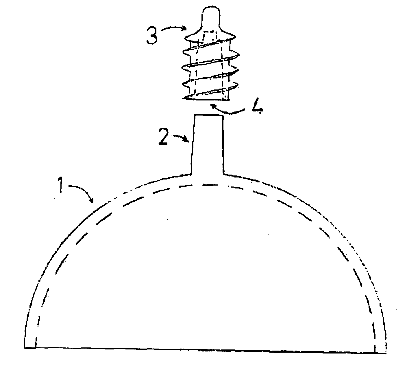
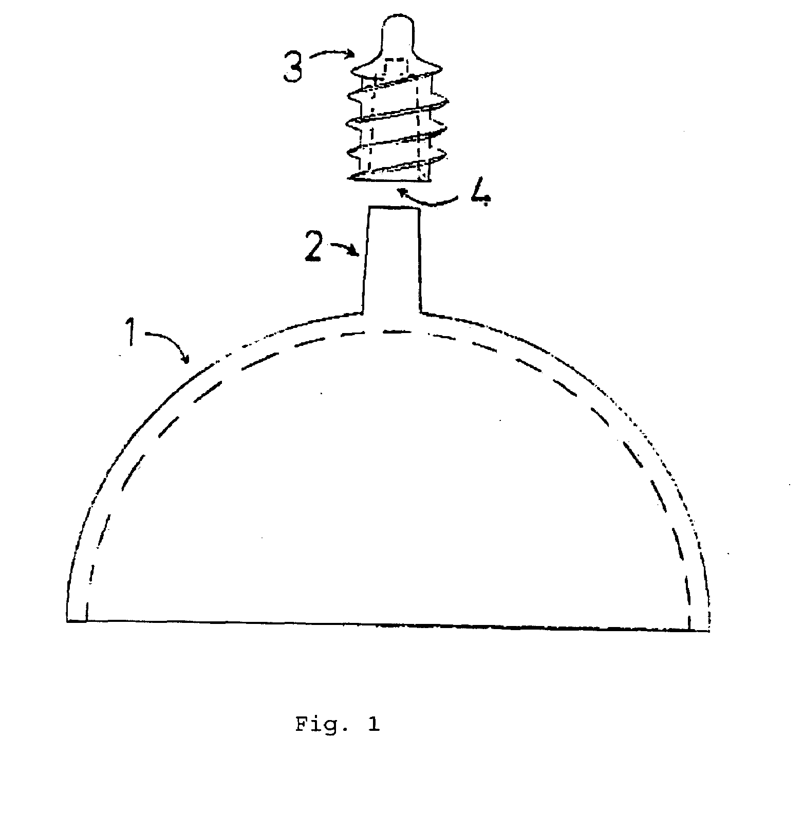
[0010]Referring now to FIG. 1, a perspective view is shown of an acetabular cup 1 and an acetabular fixation screw 3. The acetabular cup 1 is generally hemispherical and has a hollow center as indicated by the dashed line. The acetabular cup 1 is provided at a dome region thereof with a taper 2. In the illustrated embodiment, the cup portion and ...


PUM


Abstract

A fixation technique is provided whereby a solid metal acetabular cup, such as is used with hip resurfacing implants, or so called “metal on metal” bearings used with traditional total hip replacement, which do use supplemental screw fixation, can achieve immediate fixation to the acetabulum using a acetabular fixation screw, which couples to an acetabular metal cup by way of a precision taper coupling (tapered interference fit) between the fixation screw and the acetabular cup. Under normal loading, the cold weld achieved between the two surfaces is stable, and disassociation between the two metal surfaces can be achieved only with significant force.

Description

FIELD OF THE INVENTION[0001]The present invention relates to joint implants, particularly hip joint implants.BACKGROUND OF THE INVENTION[0002]Prior art efforts for acetabular cup fixation have included peripheral fins, dual geometry cups, spikes on the outer surface of the cup, porous outside cup surfaces which create friction between bone and socket, and a so called “press fit technique” whereby an acetabular cup is impacted into the bony acetabulum which has been reamed to a size 1-2 mm smaller than the cup. These techniques at times do not achieve adequate fixation, and cup malpositioning or “spin-out” is not uncommon. Refinements to the press fit technique include small spikes on the outer surface of the cup, which are driven into the bony acetabulum. While these measures allow for better stabilization, they give rise to difficulties with cup positioning as well as difficulties with successfully seating the acetabular component firmly against the bony acetabulum, due to displace...

Claims


Application Information

Patent Timeline
IPC IPC(8): A61F2/32A61B19/00A61B17/04
CPCA61F2/30749A61F2/34A61F2002/30332A61F2002/3085A61F2002/30878A61F2002/3092A61F2310/00179A61F2002/3416A61F2002/3446A61F2220/0008A61F2220/0033A61F2310/00023A61F2310/00029A61F2002/3414
Inventor URE, KEITH J.
Owner URE KEITH J
Why Eureka
Try Eureka