
Exhaust manifold

Active Publication Date: 2010-05-27
TOYOTA JIDOSHA KK
View PDF3 Cites 6 Cited by
  • Summary
  • Abstract
  • Description
  • Claims
  • Application Information

AI Technical Summary

Benefits of technology

[0014]The invention provides an exhaust manifold that is able to prevent damage to a branch portion by reducing stress of branch pipe portions of an inner pipe when the inner pipe is subjected to high-temperature exhaust gas, and that can improve reliability.

Problems solved by technology

However, when the temperature of the catalyst is lower than its active temperature, it is difficult to ensure favorable exhaust gas purification performance.
However, a difference in thermal expansion increases between the thin common inner pipe exposed to high-temperature exhaust gas and the thick common outer pipe exposed to outside air.
For this reason, the branched portion of the branch pipe portions forms cracks and is damaged, thus decreasing reliability of the exhaust manifold.

Method used


Image

  • Exhaust manifold
  • Exhaust manifold
  • Exhaust manifold

Examples


Embodiment Construction

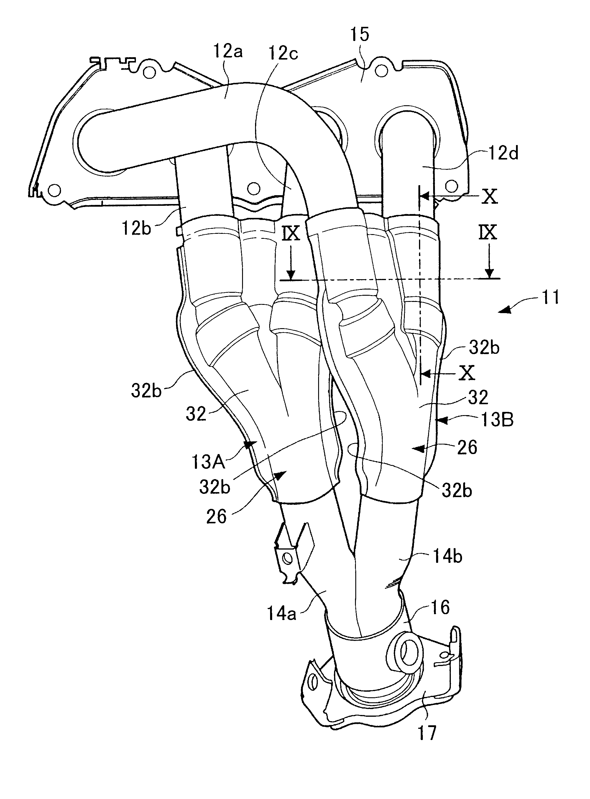
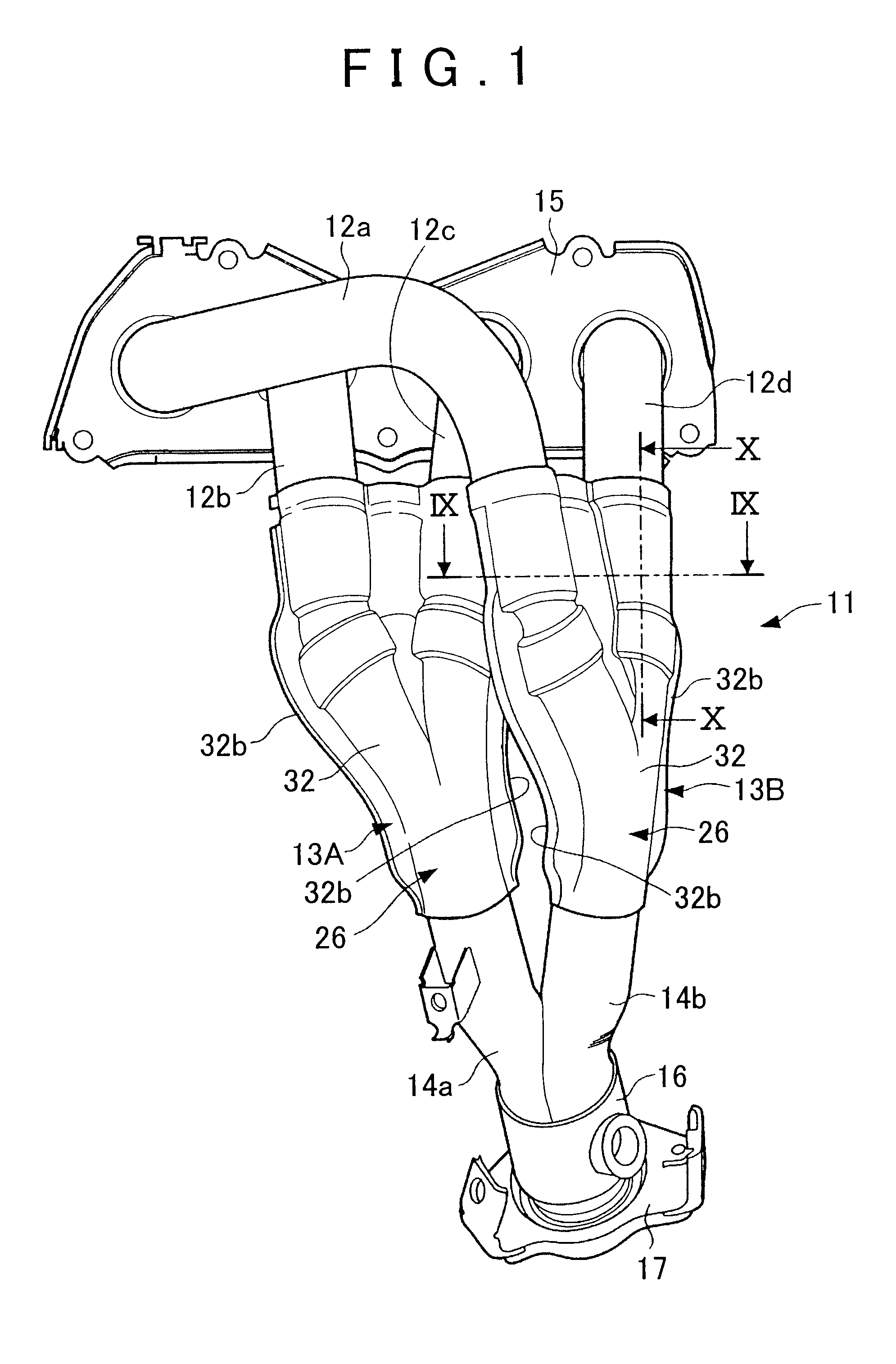
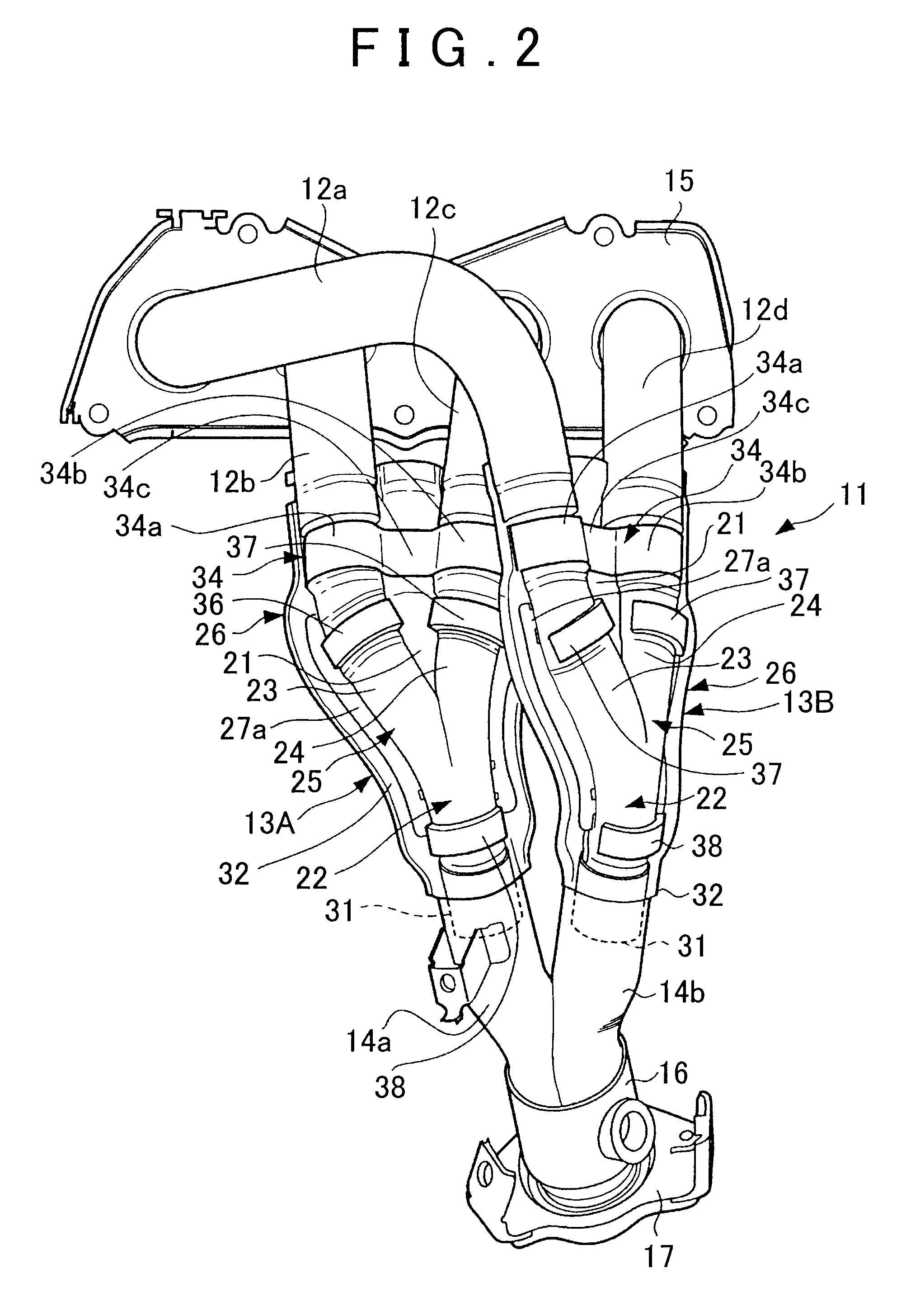
[0028]Hereinafter, an exhaust manifold according to an embodiment of the invention will be described with reference to the accompanying drawings. FIG. 1 to FIG. 11 are views that show the exhaust manifold according to the embodiment of the invention. Note that FIG. 1 is a front view of the exhaust manifold, FIG. 2 is a front view of the exhaust manifold in a state where a half of an outer pipe of each double collecting pipe is removed, FIG. 3 is an exploded view of the double collecting pipe, FIG. 4 is a front view of the inner pipe, FIG. 5 is a rear view of the inner pipe, FIG. 6 is a side view of the inner pipe, FIG. 7 is a front view of the double collecting pipe in a state where a half of the outer pipe is removed, FIG. 8 is a rear view of the double collecting pipe in a state where the other half of the outer pipe is removed, FIG. 9 is a cross-sectional view taken along the line IX-IX in FIG. 1, FIG. 10 is a cross-sectional view taken along the line X-X in FIG. 1, and FIG. 11 i...


PUM


Abstract

An exhaust manifold includes: a double collecting pipe having an inner pipe, including a collecting pipe portion and branch pipe portions, and an outer pipe, covering the collecting and branch pipe portions and thicker than the inner pipe; and an inner pipe retainer having semi-circular portions and a connecting portion, and thicker than the inner pipe and thinner than the outer pipe. The inner pipe retainer connects the inner and outer pipes with a gap therebetween. Exhaust gas from exhaust ports of a set of cylinders is introduced into the collecting pipe portion through the branch pipe portions. The total spot-welded area of the outer peripheral portions of the branch pipe portions and the inner peripheral portions of the semi-circular portions is larger than that of the inner peripheral portion of the outer pipe and the outer peripheral portions of the semi-circular portions.

Description

INCORPORATION BY REFERENCE[0001]The disclosure of Japanese Patent Application No. 2008-299741 filed on Nov. 25, 2008 including the specification, drawings and abstract is incorporated herein by reference in its entirety.BACKGROUND OF THE INVENTION[0002]1. Field of the Invention[0003]The invention relates to an exhaust manifold and, more specifically, to an exhaust manifold that includes a double collecting pipe that guides exhaust gas from exhaust ports of a set of cylinders.[0004]2. Description of the Related Art[0005]Generally, an internal combustion engine (engine) has a catalyst arranged in an exhaust passage to purify exhaust gas. However, when the temperature of the catalyst is lower than its active temperature, it is difficult to ensure favorable exhaust gas purification performance. Therefore, it is necessary to promptly heat the catalyst to the active temperature, for example, when the engine is started.[0006]Japanese Patent Application Publication No. 7-224649 (JP-A-7-2246...

Claims


Application Information

Patent Timeline
IPC IPC(8): F01N13/00F16L9/14
CPCF01N13/08F01N2450/22F01N13/1872F01N13/102
Inventor MURAKAMI, NOBUYUKIHOSOI, HIROSHIYAGI, KATSUMIJINNO, KIMIHIROFUKAGAWA, TATSUKI
Owner TOYOTA JIDOSHA KK
Learn More