Vacuum Sealed Paint Roller Cover Package and Method of Making the Same

a paint roller cover and vacuum sealing technology, applied in the field to achieve the effect of reducing shipping and display shelf space volumes, increasing manufacturing or packaging complexity of paint roller covers, and durable and long-lasting

Active Publication Date: 2010-05-27
SEAMLESS TECH
View PDF5 Cites 9 Cited by
  • Summary
  • Abstract
  • Description
  • Claims
  • Application Information

AI Technical Summary

Benefits of technology

[0027]Since the compactly packaged paint roller cover of the present invention requires substantially less volume to ship and display than a conventional paint roller cover, it will be appreciated that it presents significant cost savings due to the increased shipping efficiency as well as being advantageous in the eyes of retailers due to the reduced shelf space required to display it. Following purchase, a user opens the vacuum sealed plastic bag and the semi-rigid paint roller cover therein tends to resiliently resume its round cross-section.
[0028]It may therefore be seen that the present invention teaches a compactly packaged paint roller cover that requires significantly reduced shipping and display shelf space volumes. The compactly packaged paint roller cover of the present invention allows the packaging of paint roller covers in a lower volume without having an adverse effect on the quality of the paint roller covers. In addition, the compactly packaged paint roller cover of the present invention does not substantially increase the manufacturing or packaging complexity required to manufacture and package them.
[0029]The compactly packaged paint roller cover of the present invention is of a construction which is both durable and long lasting, and the packaged paint roller covers require no special handling to be provided during shipping, display, or storage prior to the paint roller covers being used. The compactly packaged paint roller cover of the present invention is inexpensive to manufacture and package to enhance its market appeal and to thereby afford it the broadest possible market. Finally, all of the aforesaid advantages and objectives of the compactly packaged paint roller cover of the present invention are achieved without incurring any substantial relative disadvantage.

Problems solved by technology

This is only practical assuming that the contents of the vacuum sealable plastic bag are both compressible and resilient.

Method used


Image

  • Vacuum Sealed Paint Roller Cover Package and Method of Making the Same
  • Vacuum Sealed Paint Roller Cover Package and Method of Making the Same
  • Vacuum Sealed Paint Roller Cover Package and Method of Making the Same

Examples


Embodiment Construction

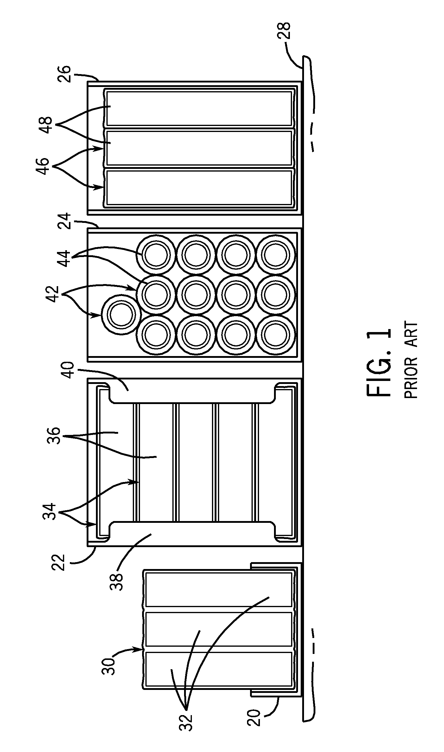
[0043]Referring initially to FIG. 1, a plurality of conventional paint roller covers are shown in four display cartons 20, 22, 24, and 26, all of which are located on a display shelf 28. The display carton 20 contains a plurality of three-packs 30 of paint roller covers 32, which are oriented vertically in the display carton 20. The display carton 22 contains a plurality of horizontally oriented single packages 34 each containing a single paint roller cover 36 that are oriented parallel to the open front-facing side of the display carton 22. It may be seen that the display carton 22 has a pair of flaps 38 and 40 extending into its otherwise open front-facing side to retain the single packages 34 each containing a single paint roller cover 36 therein.

[0044]The display carton 24 contains a plurality of horizontally oriented single packages 42 each containing a single paint roller cover 44 that are oriented orthogonally to the open front-facing side of the display carton 24. Finally, t...


PUM


Abstract

A compactly packaged paint roller cover and a method of compactly packaging a paint roller cover are disclosed which require significantly reduced shipping and display shelf space volumes. A semi-rigid paint roller cover manufactured from a small diameter tubular knitted pile fabric is placed within a vacuum sealable plastic bag, which is subsequently evacuated and sealed, collapsing the semi-rigid paint roller cover to a flattened configuration. Such compactly packaged paint roller covers require significantly reduced shipping and display shelf space volumes. To use the compactly packaged paint roller cover, the vacuum sealed plastic bag is opened upon which the semi-rigid paint roller cover resiliently resumes its round cross-section.

Description

IDENTIFICATION OF RELATED APPLICATIONS[0001]This patent application is: a. a continuation-in-part of copending U.S. patent application Ser. No. 12 / 116,022, filed on May 6, 2008, entitled “Tubular Cut Pile Knit Fabric for Paint Roller Covers,” which is in turn a continuation-in-part of U.S. patent application Ser. No. 11 / 740,119, filed on Apr. 25, 2007, now U.S. Pat. No. 7,503,191, issued on Mar. 17, 2009, entitled “Tubular Sliver Knit Fabric for Paint Roller Covers;” b. a continuation-in-part of copending U.S. patent application Ser. No. 12 / 015,612, filed on Jan. 17, 2008, entitled “Method of Manufacturing Paint Roller Covers From a Tubular Fabric Sleeve;” c. a continuation-in-part of copending U.S. patent application Ser. No. 12 / 100,050, filed on Apr. 9, 2008, entitled “Method of Manufacturing Paint Roller Covers From a Tubular Fabric Sleeve;” d. a continuation-in-part of copending U.S. patent application Ser. No. 12 / 132,774, filed on Jun. 4, 2008, entitled “Method of Manufacturing...

Claims


Application Information

Patent Timeline
Patent Type & Authority Applications(United States)
IPC IPC(8): B65D85/00B65D33/00B65B31/04
CPCD04B1/02B05C17/02
Inventor SINYKIN, DANIEL L.
Owner SEAMLESS TECH
Why Eureka
Try Eureka