
External left ventricular assist device for treatment of congestive heart failure

a technology of left ventricular assist and congestive heart failure, which is applied in the field of treatment of congestive heart failure, can solve the problems of resistance to air flow in and out of the shell, and achieve the effect of lowering the blood pressure in the affected regions

Inactive Publication Date: 2008-02-21
RASTEGAR JAHANGIR +1
View PDF26 Cites 13 Cited by
  • Summary
  • Abstract
  • Description
  • Claims
  • Application Information

AI Technical Summary

Benefits of technology

[0027] The present invention overcomes these disadvantages through use of a uniquely designed applicator housing with an internal air distribution system. The applicator is custom fit to the limb and therefore requires much less air volume to operate than prior art applications. Since less air volume is needed to operate the housing, much smaller capacity, much lighter and less expensive air pumps are required. Because the applicator housing is assembled in situ from deformable components which are rigidified as they are secured on the patient, and thus can be customized for each patient, the necessity of inventorying large numbers of prefabricated housing components is eliminated while, at the same time, the preciseness of the fit for each individual patient is greatly enhanced.
[0029] Further, by minimizing the volume of air required, substantially the same air can be rapidly pumped in and out of the housing to generate positive and / or negative relative pressures in a relatively closed system. This provides an efficient means to control the air pressure, and also permits the air temperature to be closely controlled. Controlling the temperature of the air is important because warmer air promotes vascular dilation, resulting in greater blood flow and hence more efficient operation of the apparatus.

Problems solved by technology

The main limitation in employing such a small gap between the shell and limb surface is the resistance to the air flow in and out of the shell.

Method used


Image

  • External left ventricular assist device for treatment of congestive heart failure
  • External left ventricular assist device for treatment of congestive heart failure
  • External left ventricular assist device for treatment of congestive heart failure

Examples


Embodiment Construction

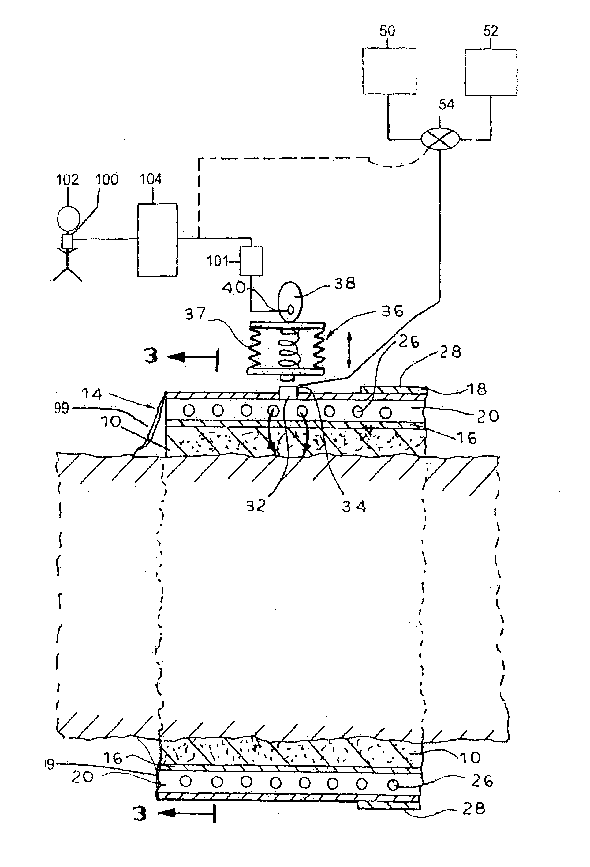
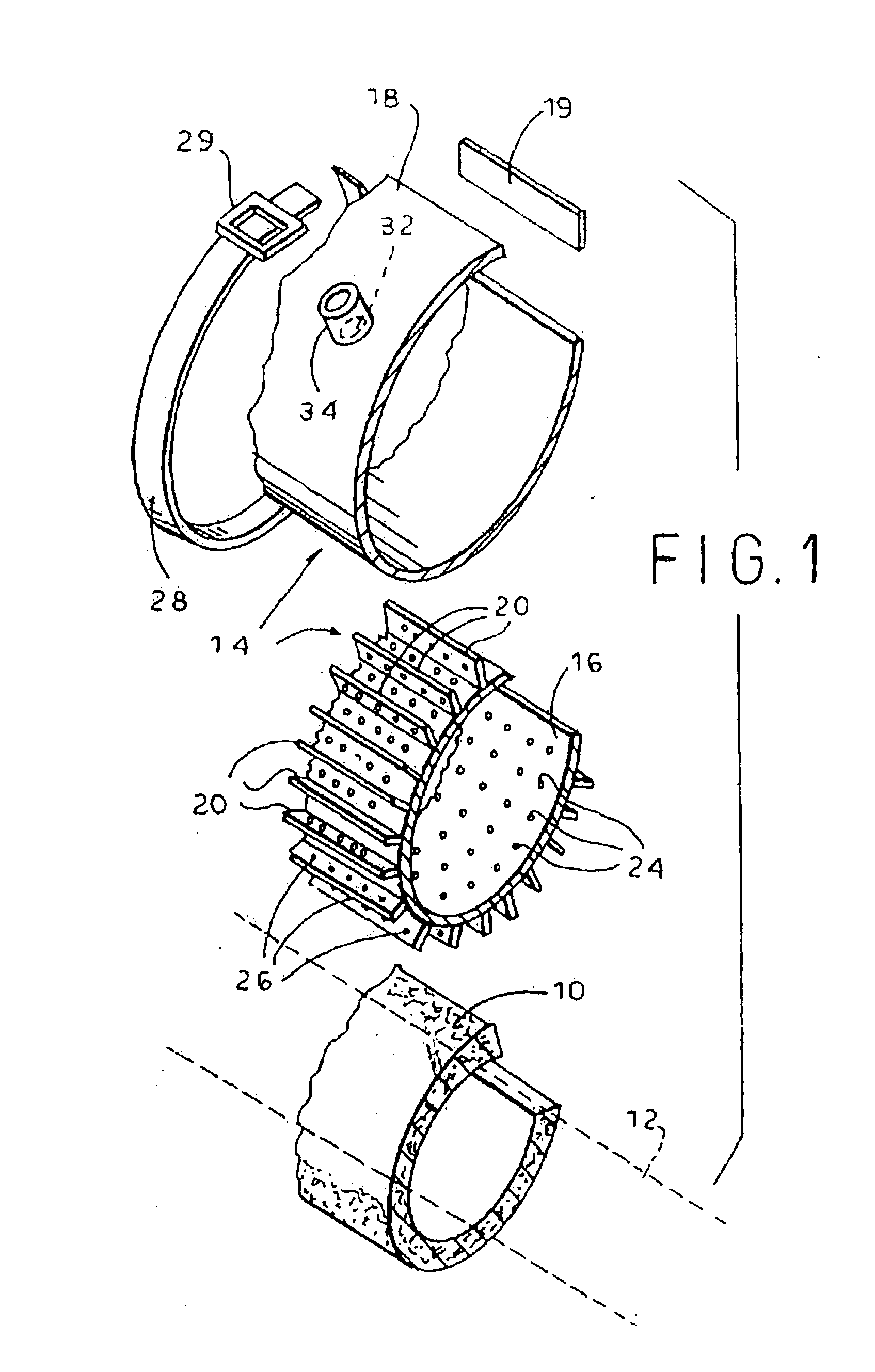
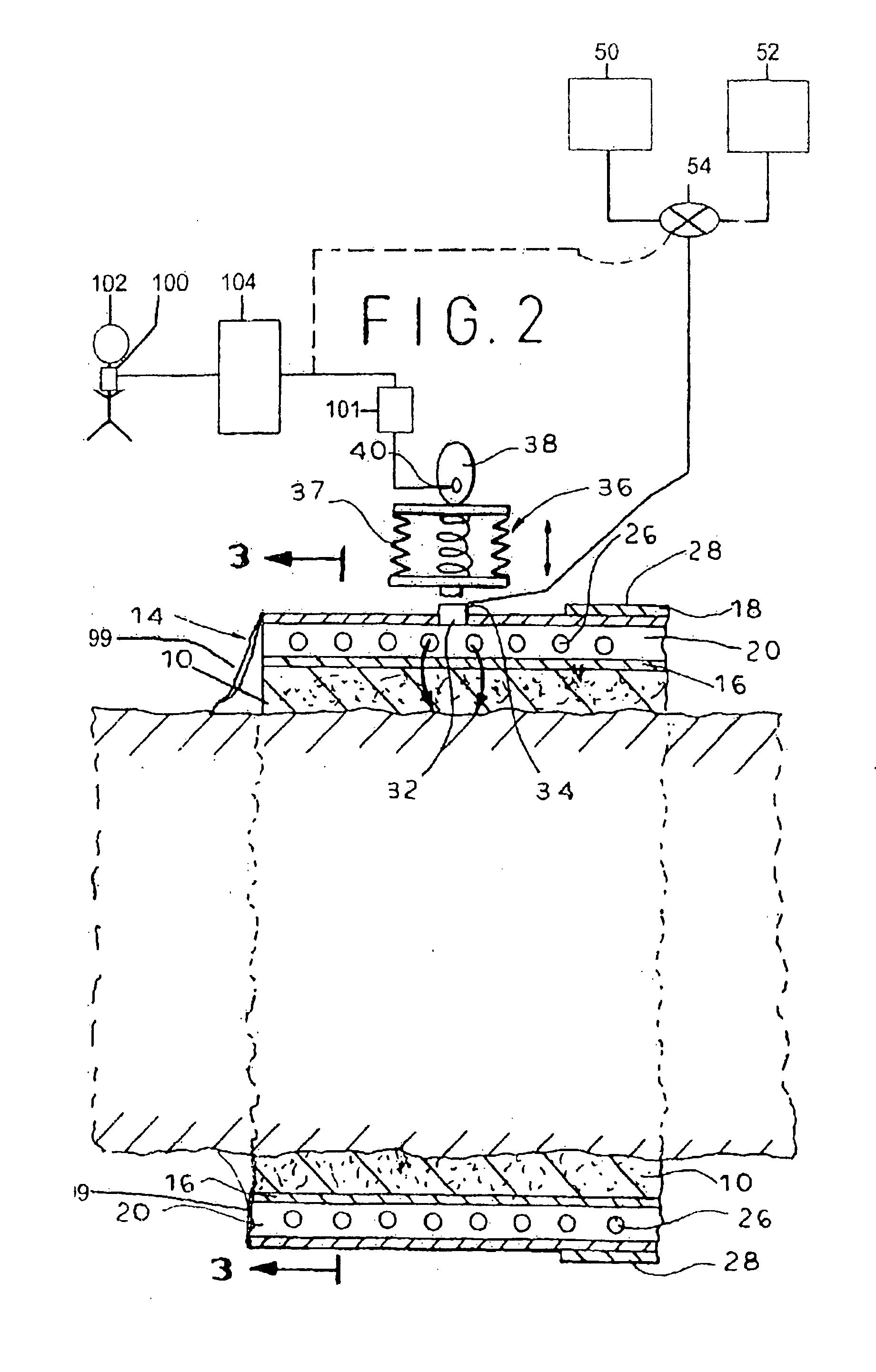
[0096] The first preferred embodiment of the invention, as illustrated in FIGS. 1, 2 and 3, comprises a tube-like housing, a typical precut section of which is illustrated. The housing is adapted to be assembled in situ, and custom fitted to a limb, such as an arm or leg or to entire lower portion of the body, including the thighs and buttocks. The housing consists of a flexible, air permeable inner layer 10 composed of a sheet of fabric, felt or sponge-like material. Inner layer 10 is placed around the limb 12 and trimmed to size using a scissor or blade.

[0097] Around inner layer 10 is tightly fitted a hollow shell 14 which is initially deformable enough to closely conform to the contours of the limb. After shell 14 is sealed and secured in place around the limb as described below, it will become relatively rigid.

[0098] Shell 14 consists of an interior wall 16 and an exterior wall 18. Walls 16 and 18 are spaced apart by a plurality of upstanding spacer elements 20, so as to form ...


PUM


Abstract

The invention provides a treatment for congestive heart failure (CHF) in a patient. At least one pressure applicator is arranged externally around a body segment of the patient. Negative pressure, relative to atmospheric pressure, is applied to the body segment of the patient during cardiac systole using the pressure applicator, thereby reducing ventricular afterload in the patient. The negative pressure to the body segment of the patient is removed during cardiac diastole.

Description

CROSS-REFERENCE TO RELATED APPLICATIONS [0001] This application is a continuation-in-part of U.S. application Ser. No. 11 / 009,222, filed Dec. 10, 2004, which is a continuation of U.S. application Ser. No. 09 / 851,930, filed May 10, 2001, now U.S. Pat. No. 6,846,294, issued Jan. 25, 2005, the disclosures of which are incorporated by reference herein. This application also claims the priority of U.S. Provisional Application No. 60 / 808,482, filed May 25, 2006, the disclosure of which is incorporated by reference herein.BACKGROUND OF THE INVENTION [0002] The present invention relates to the treatment of congestive heart failure using an external counterpulsation cardiac assist device which functions by applying positive and / or negative relative pressure to the limbs and more particularly, to the treatment of congestive heart failure using a relatively rigid, sealed housing for applying positive and / or negative relative (to atmospheric) pressure to the limbs in counterpulsation with heart...

Claims


Application Information

Patent Timeline
Patent Type & Authority Applications(United States)
IPC IPC(8): A61H7/00
CPCA61H9/0092A61H9/0078
Inventor RASTEGAR, JAHANGIRSOROFF, HARRY
Owner RASTEGAR JAHANGIR
Learn More