High-voltage electrical component unit for vehicles

a technology for electrical components and vehicles, applied in the direction of electric propulsion mounting, electric devices, batteries/cells, etc., can solve the problems of unfavorable phenomenon, easy collapse of power distribution blocks, and difficulty in keeping components aligned with each other, so as to improve safety during maintenance of inverters or dc-dc converters.

Active Publication Date: 2010-05-27
HONDA MOTOR CO LTD
View PDF5 Cites 33 Cited by
  • Summary
  • Abstract
  • Description
  • Claims
  • Application Information

AI Technical Summary

Benefits of technology

[0028]In the high-voltage electrical component unit described in (7), since electrical connection between the electrical storage device and the power control block via the functional section for protecting the electrical storage device is blocked when the conductive functional component is removed, safety during maintenance of the inverter or the DC-DC converter can further be improved.

Problems solved by technology

Therefore, if the power distribution block and the electrical storage device are temporarily fastened to each other with the locking claw being engaged to the groove without being turned upside down, it is difficult to keep these components aligned with each other (i.e., the power distribution block collapses easily).
This phenomenon is unfavorable from the viewpoint of protection of the high-voltage electrical component unit (the power control block).
In this case, however, it is difficult to keep the power distribution block aligned with the assembly block in a temporarily fastened state by only the locking claw of the power distribution block engaged to the groove formed in the electrical storage device.
Especially in the latter high-voltage electrical component unit, since the electrical storage device and the power control block are stacked vertically to increase height thereof, the power distribution block assembled thereto may easily collapse during temporary fastening because the position of the center of gravity of the power distribution block becomes high.

Method used


Image

  • High-voltage electrical component unit for vehicles
  • High-voltage electrical component unit for vehicles
  • High-voltage electrical component unit for vehicles

Examples


Embodiment Construction

[0039]Referring now to the drawings, an embodiment of the invention will be described.

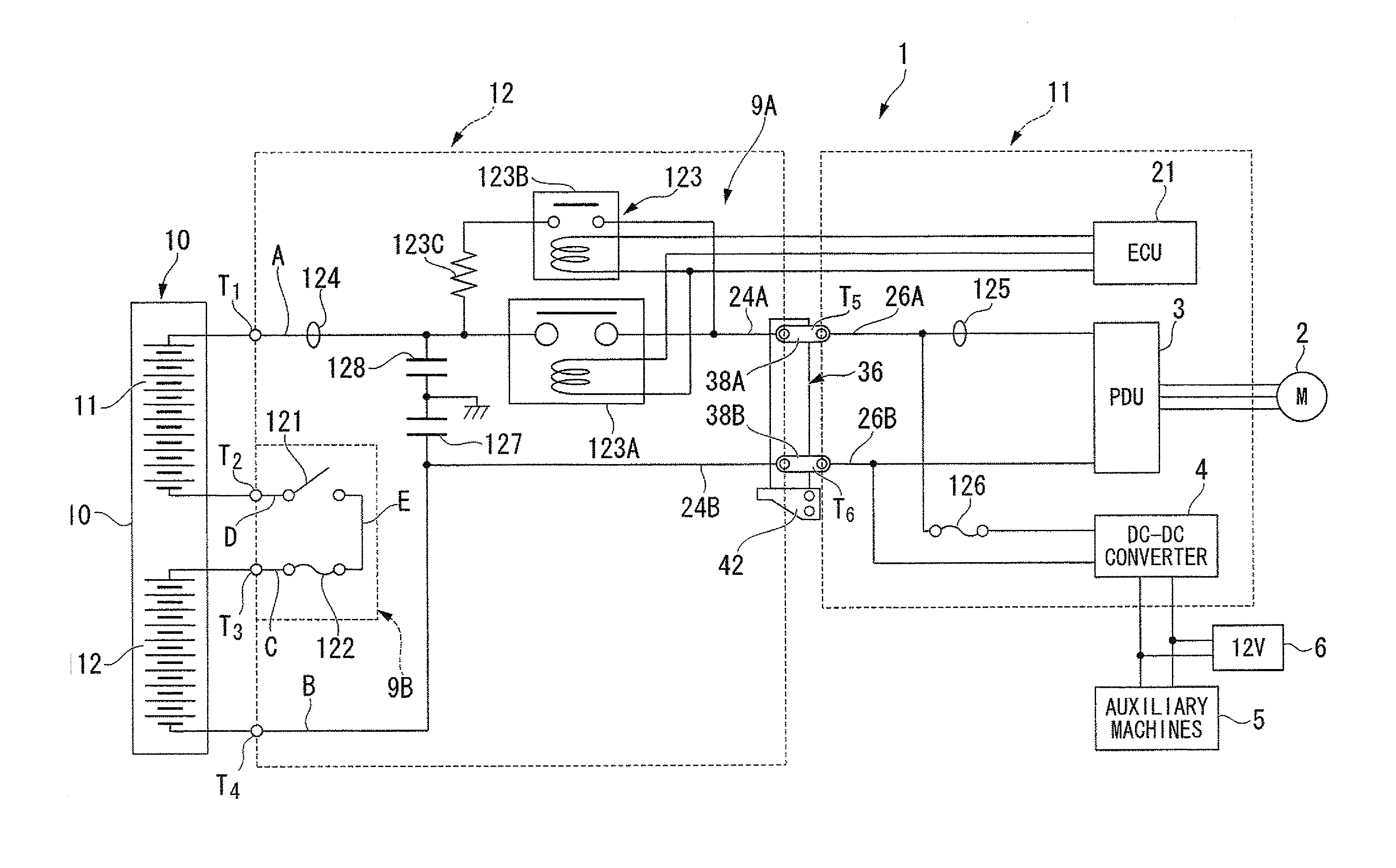
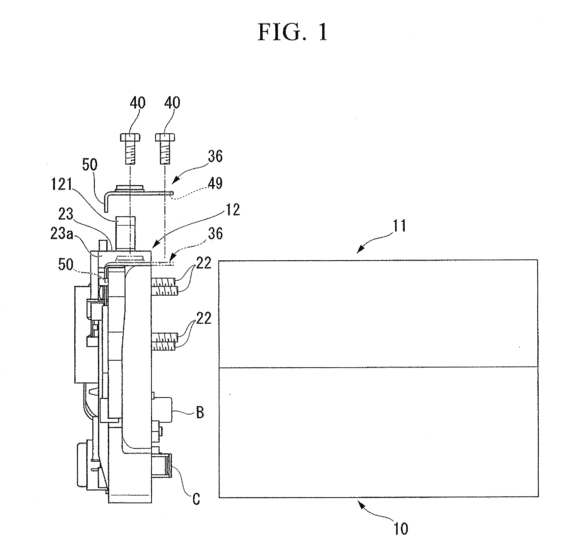
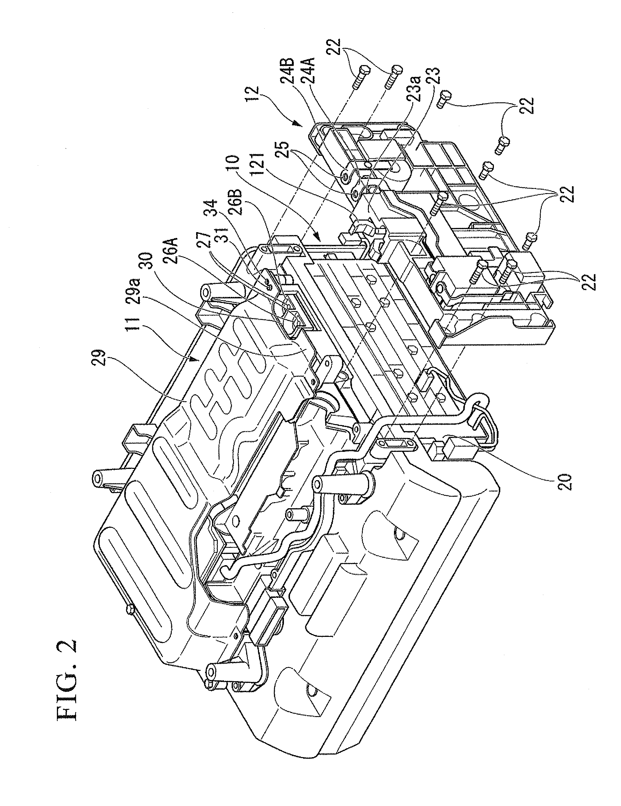
[0040]A high-voltage electrical component unit1 for vehicles according to the present embodiment (hereinafter, referred to as “high-voltage electrical component unit 1”) is used as a high-voltage power supply for driving vehicles, such as hybrid vehicles and fuel cell vehicles. As illustrated in FIGS. 1 to 3, the high-voltage electrical component unit 1 includes an electrical storage device 10 (i.e., a high-voltage battery), a power control block 11 and a power distribution block 12. The electrical storage device 10 keeps high-voltage electric power used by a vehicle. The power control block 11 mainly controls input and output electric power (i.e., supplied power and regenerative power) of the electrical storage device 10. The power distribution block 12 electrically connects the electrical storage device 10 and the power control block 11.

[0041]FIG. 4 is an electrical circuit diagram of the high-vo...


PUM


Abstract

Provided is a high-voltage electrical component unit for vehicles, including: an electrical storage device; a power control block disposed above the electrical storage device for controlling input-output power of the electrical storage device; and a power distribution block disposed across both side portions of the electrical storage device and the power control block for electrically connecting the electrical storage device and the power control block, the electrical storage device, the power control block and the power distribution block being fastened to one another, wherein a temporarily fastening section is provided at a separately-provided conductive functional component which electrically connects a connection terminal of the power distribution block and a connection terminal of the power control block, the temporarily fastening section engaging to both the power control block and the power distribution block to hold relative positions thereof.

Description

BACKGROUND OF INVENTION[0001]1. Technical Field of the Invention[0002]The present invention relates to a high-voltage electrical component unit for vehicles that supplies electric power to, for example, a motor for driving a vehicle.[0003]Priority is claimed on Japanese Patent Application No. 2008-299283, filed Nov. 25, 2008, the content of which is incorporated herein by reference.[0004]2. Background Art[0005]Hybrid vehicles and fuel cell vehicles have a high-voltage battery (i.e., a high-voltage electrical storage device) mounted thereon as a power supply for driving vehicles in addition to a low-voltage battery as a power supply for auxiliary machines.[0006]Electric power in the high-voltage battery relays battery protection circuits, such as a contactor and a fuse, and is output to a motor for driving a vehicle via an inverter-based power driven unit (PDU). The electric power is partially stepped down by a DC-DC converter and is charged in the low-voltage battery.[0007]A high-vo...

Claims


Application Information

Patent Timeline
Patent Type & Authority Applications(United States)
IPC IPC(8): B60L1/00
CPCB60K1/00Y02T10/7005B60L11/18B60L50/60Y02T10/70
Inventor FUKAZU, TOMOHIROTAKIZAWA, HIROYASU
Owner HONDA MOTOR CO LTD
Why Eureka
Try Eureka