Wavelength sweep control

a sweep control and wavelength technology, applied in the direction of optical radiation measurement, instruments, spectrometry/spectrophotometry/monochromators, etc., can solve the problem of increasing the amount of interrogation time spent covering wavelengths that produce no useful signals

Active Publication Date: 2010-05-27
WEATHERFORD TECH HLDG LLC
View PDF7 Cites 94 Cited by
  • Summary
  • Abstract
  • Description
  • Claims
  • Application Information

AI Technical Summary

Benefits of technology

[0010]One embodiment of the present invention is a method. The method generally includes filtering light emitted from an amplified spontaneous emission (ASE) source, amplifying the filtered light, and interrogating one or more optical elements with the amplified light to measure one or more parameters.
[0011]Another embodiment of the present invention provides an apparatus for interrogating one or more optical elements. The apparatus generally includes an ASE source for emitting light, a filter for filtering the light emitted by the ASE source, and an amplifier for amplifying the filtered light, such that the amplified light is used to interrogate the optical elements.
[0012]Yet another embodiment of the present invention is a method. The method generally includes providing light, wherein a wavelength of the light is changed according to a sweep function; interrogating one or more reflective optical elements with the wavelength-swept light to produce reflected optical signals; filtering the reflected optical signals, wherein a bandpass wavelength range is changed based on the sweep function to follow the changes in the light's wavelength; and receiving the filtered, reflected optical signals for processing.
[0013]Yet another embodiment of the present invention provides an apparatus. The apparatus generally includes a light source configured to change a wavelength of the light according to a sweep function; one or more reflective optical elements configured to receive the wavelength-swept light from the light source and to reflect portions of the light at characteristic wavelengths producing reflected optical signals; a tunable bandpass filter configured to filter the reflected optical signals, wherein a bandpass wavelength range of the filter is changed based on the sweep function to follow the changes in the light's wavelength; and a receiver for processing the filtered, reflected optical signals.

Problems solved by technology

These guard-bands increase the total range of wavelengths scanned, thereby increasing the amount of interrogation time spent covering wavelengths that produce no useful signal.

Method used


Image

  • Wavelength sweep control
  • Wavelength sweep control
  • Wavelength sweep control

Examples


Embodiment Construction

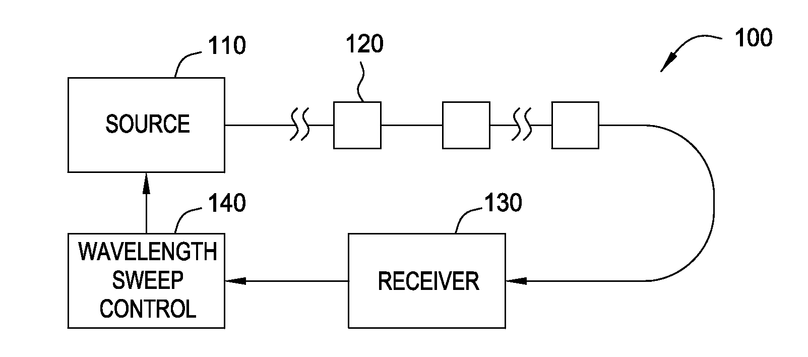
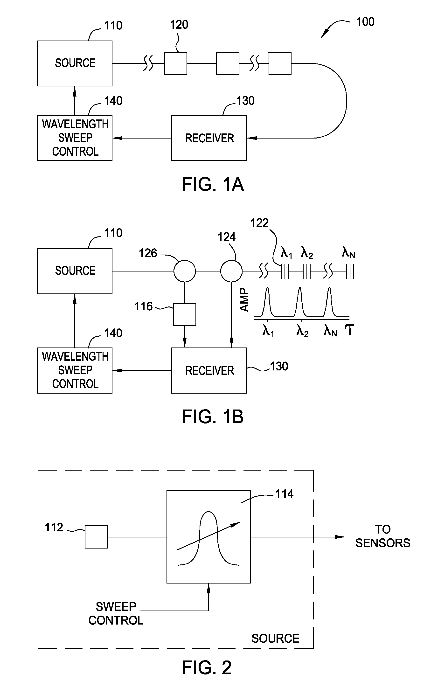
[0034]Embodiments of the present invention provide for the active control of a light source used to interrogate optical elements having characteristic wavelengths distributed across a wavelength range.

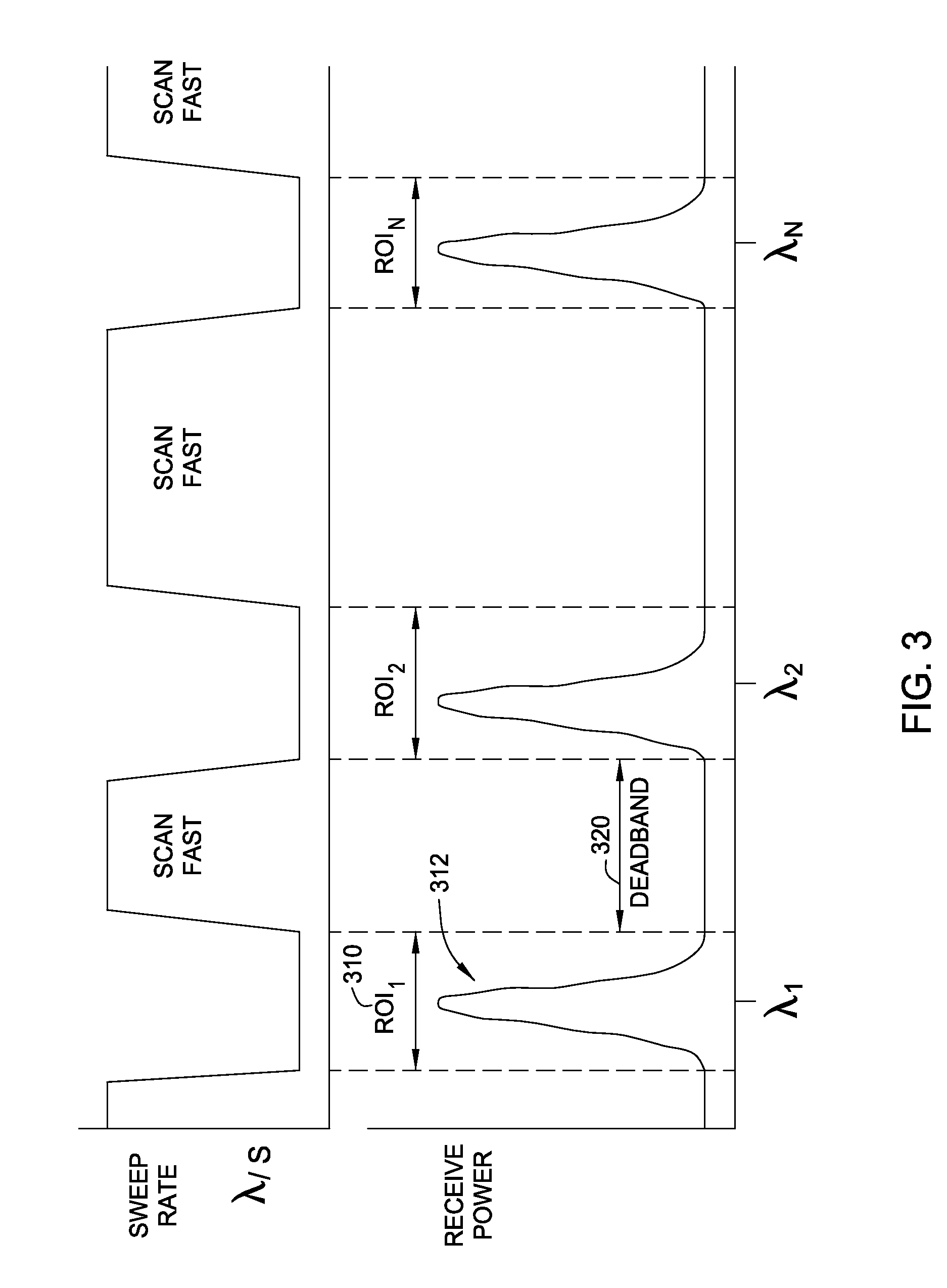
[0035]For some embodiments, this active control may include varying sweep rates across different ranges. For example, a sweep rate may be reduced in ranges containing spectral features of interest, allowing more measurements, which may lead to increased resolution. On the other hand, the sweep rate may also be increased in order to skip, or otherwise move rapidly through, other ranges (e.g., ranges absent features of interest or ranges corresponding to measured parameters that do not require as high resolution as others or as frequent measurements). Further, for some embodiments, particular ranges (sweep bands) may be adjusted, for example, to follow features of interest as they shift (e.g., change in wavelength) over time.

[0036]Different embodiments of the present invention may utiliz...


PUM


Abstract

Methods and apparatus for the active control of a wavelength-swept light source used to interrogate optical elements having characteristic wavelengths distributed across a wavelength range are provided.

Description

CROSS-REFERENCE TO RELATED APPLICATIONS[0001]This application is a continuation-in-part of co-pending U.S. patent application Ser. No. 12 / 541,770 filed Aug. 14, 2009, which is a continuation-in-part of co-pending U.S. patent application Ser. No. 11 / 755,131 filed May 30, 2007, which claims benefit of U.S. Provisional Patent Application Ser. No. 60 / 803,470, filed May 30, 2006, which are herein incorporated by reference.BACKGROUND OF THE INVENTION[0002]1. Field of the Invention[0003]Embodiments of the present invention generally relate to determination of a characteristic wavelength of an optical component and, more particularly, to techniques and apparatus for controlling the manner in which a spectral bandwidth is swept in an effort to determine the characteristic wavelength.[0004]2. Description of the Related Art[0005]Many optical components have a characteristic wavelength that may be found by interrogating the optical component with an optical source capable of producing light at ...

Claims


Application Information

Patent Timeline
Patent Type & Authority Applications(United States)
IPC IPC(8): G02B5/26G02B5/18G02B5/20
CPCG01J3/1895G01J3/4338H01S3/005H01S3/06758H01S3/06754G01J3/02G01J3/027G02B27/00H01S3/0007H01S3/1608
Inventor TAVERNER, DOMINO
Owner WEATHERFORD TECH HLDG LLC
Why Eureka
Try Eureka